Alarm clock using a PIC microcontroller
This is an alarm clock I built. It was very effective during the sort time I used it, because I programmed it to play a very annoying tune through a speaker. I actually started to wake up before the alarm went of, so other people in the house didn't wake up from the annoying pitches it played.
The JAL source code is available on my download page
Features
- Timekeeping using the PIC's timer0 interrupt
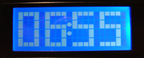
- 4x20 hd44780 compatible backlit LCD, displaying the time in big numbers (4x4 and 4x3)
- Alarm sound tune using PWM
- computer interface for synchronizing time with the web.
- (maybe battery backup (in case of a power outage...))
Status
| Timekeeping: | Rewritten in assembler. (losing one stack level, previously losing two stack levels, ISR and procedure time...) |
|---|---|
| Display: | Done. Use's Vasile's 4-line lcd routines and tables to store the texts. |
| Bignumbers: | Done. Data stored in tables. |
| Backlight: | The backlight is dimmed using the internal CCP1 module of the PIC in PWM mode. |
| Input: | Four pushbuttons on port D, handled by buttons.jal (function keypress(byte in key) return bit). |
| Alarm sound: | Uses CCP2 in PWM mode, inspired by Vasile! |
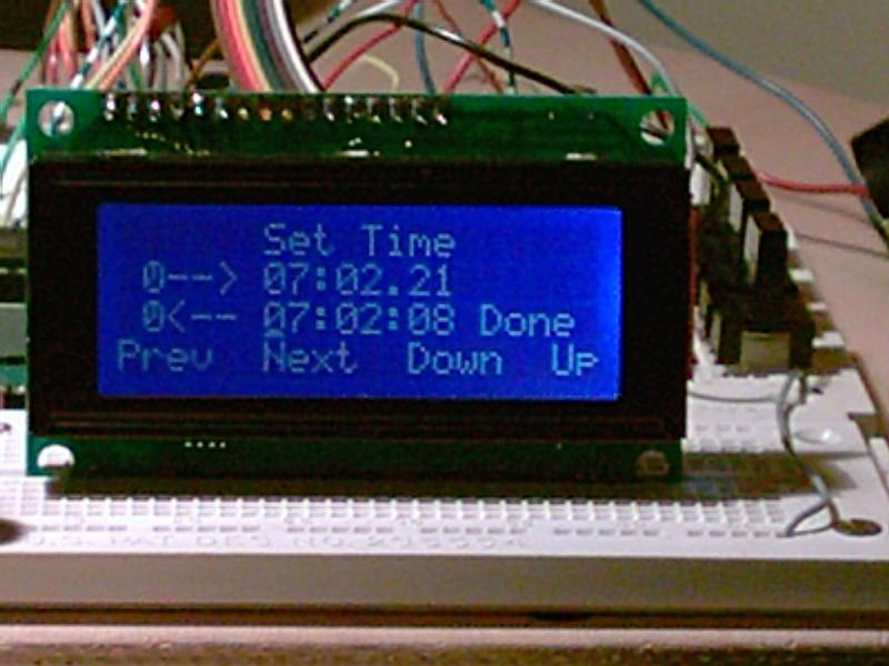
| Menu code: | Works. Can set time/alarm. |
| Computer link: | (interface code) Nothing yet. |
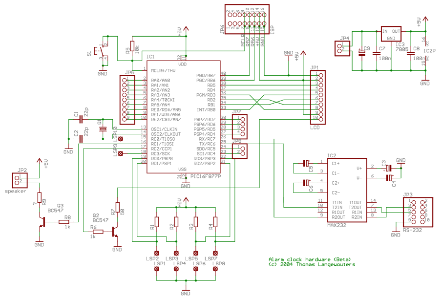
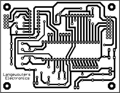
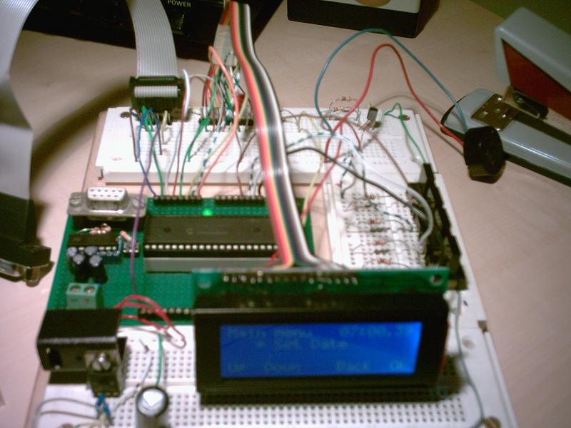
Circuit Board
Here are some details of the PCB:

A wall wart (adaptor) delivers a voltage between 7.5 and 12V to JP4. Buffer capacitors C9 and C7 ensure the voltage is clean DC (just to be sure), and IC3 lowers the voltage to 5V. C8 is provided to short high frequencies. The microcontroller is used with a 20Mhz crystal (as usual connected to two 22pF cap's), and can be reset by pushing switch S1. To connect the micro to a pc (synchronize with pc's rtc), a MAX232 TTL to rs-232 level converter is necessary. It's connected to two rows of pins, which can be connected to a flatcable with a DB9-M connector and a box connector [1]. The PCB can then be connected to a pc using a nullmodem cable. The backlight of the LCD is dimmed by the PIC's internal PWM1 module and Q2. PWM2 and Q3 drives an 8 Ohm speaker connected to JP2.
| [1] | those are often found in old pc's, where they are used to provide a second serial port on the back of the pc. |
Timekeeping
The timekeeping is done by an interrupt service routine that gets called when timer 0 overflows. The clock uses Roman's zero error method, which Roman explains on this webpage, I rewrote the code to better fit in with my own code.
To DO
- Build housing
- Design second PCB with a dedicated real time clock (Dallas or I2C)
- Store alarm time in EEPROM memory
- Implement mobile phone ring tones as alarm sounds :)
- Make a system of light bulbs that fade in to reach full brightness when the alarm goes off over a given period. (Like some people use to wake up animals)
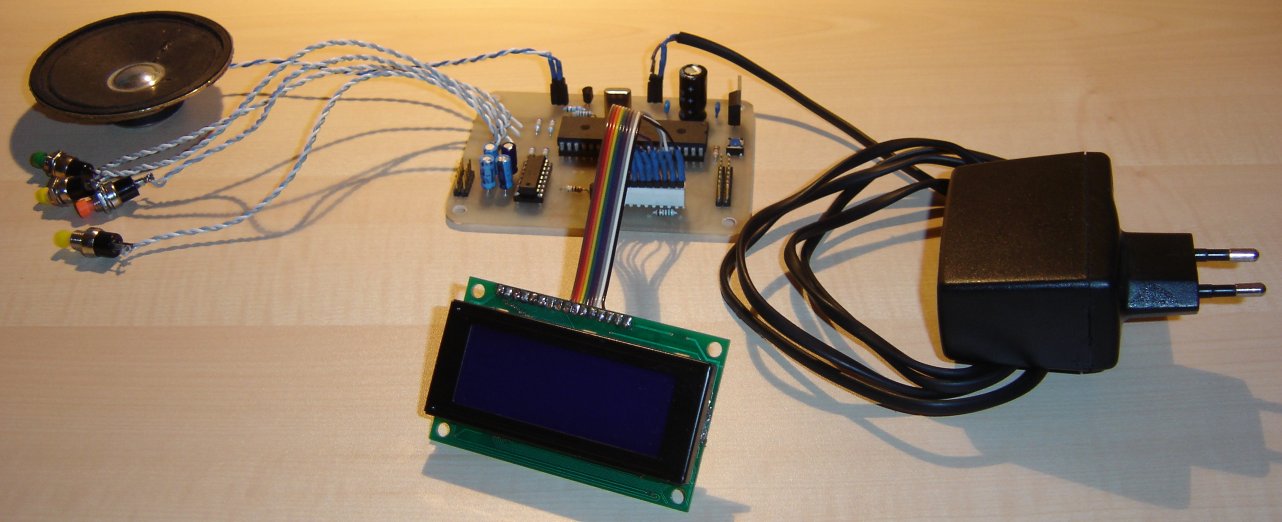
Pictures
Finished without housing
The clock geheel.jpg | 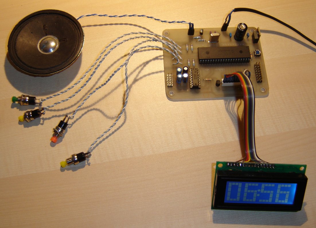
The clock geheelboven.jpg | 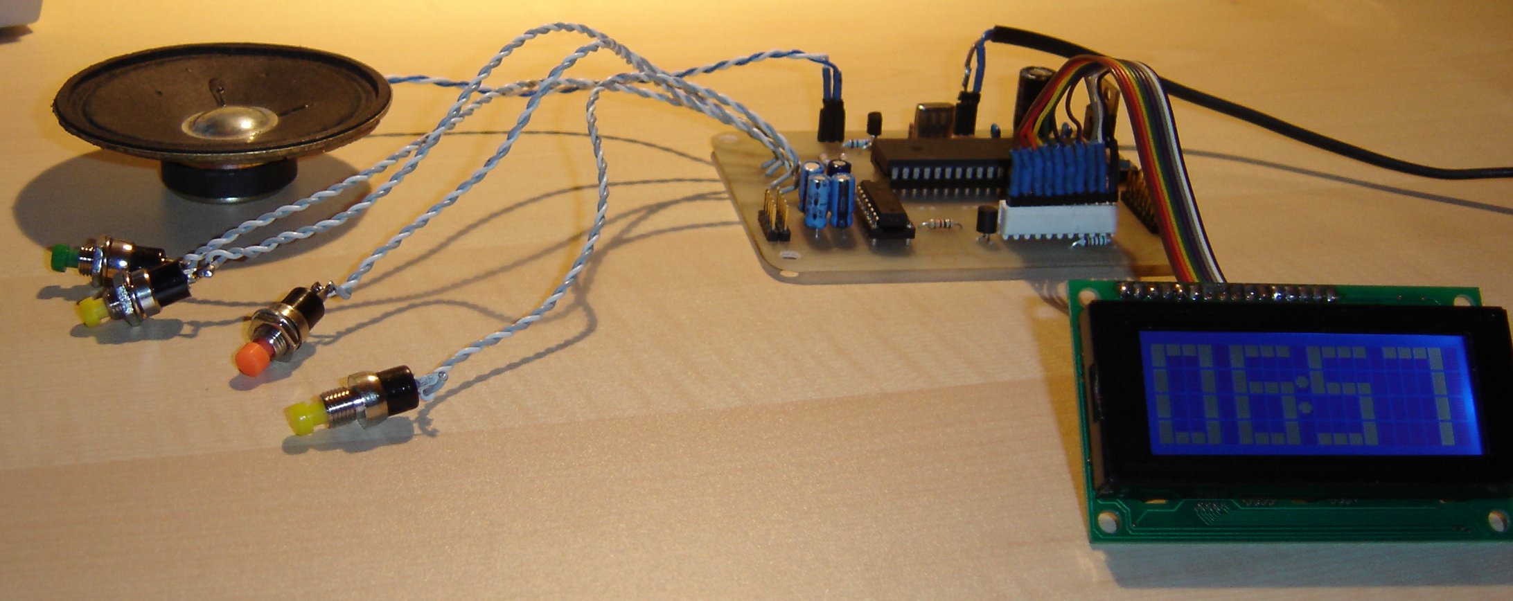
The clock geheelschuin.jpg | 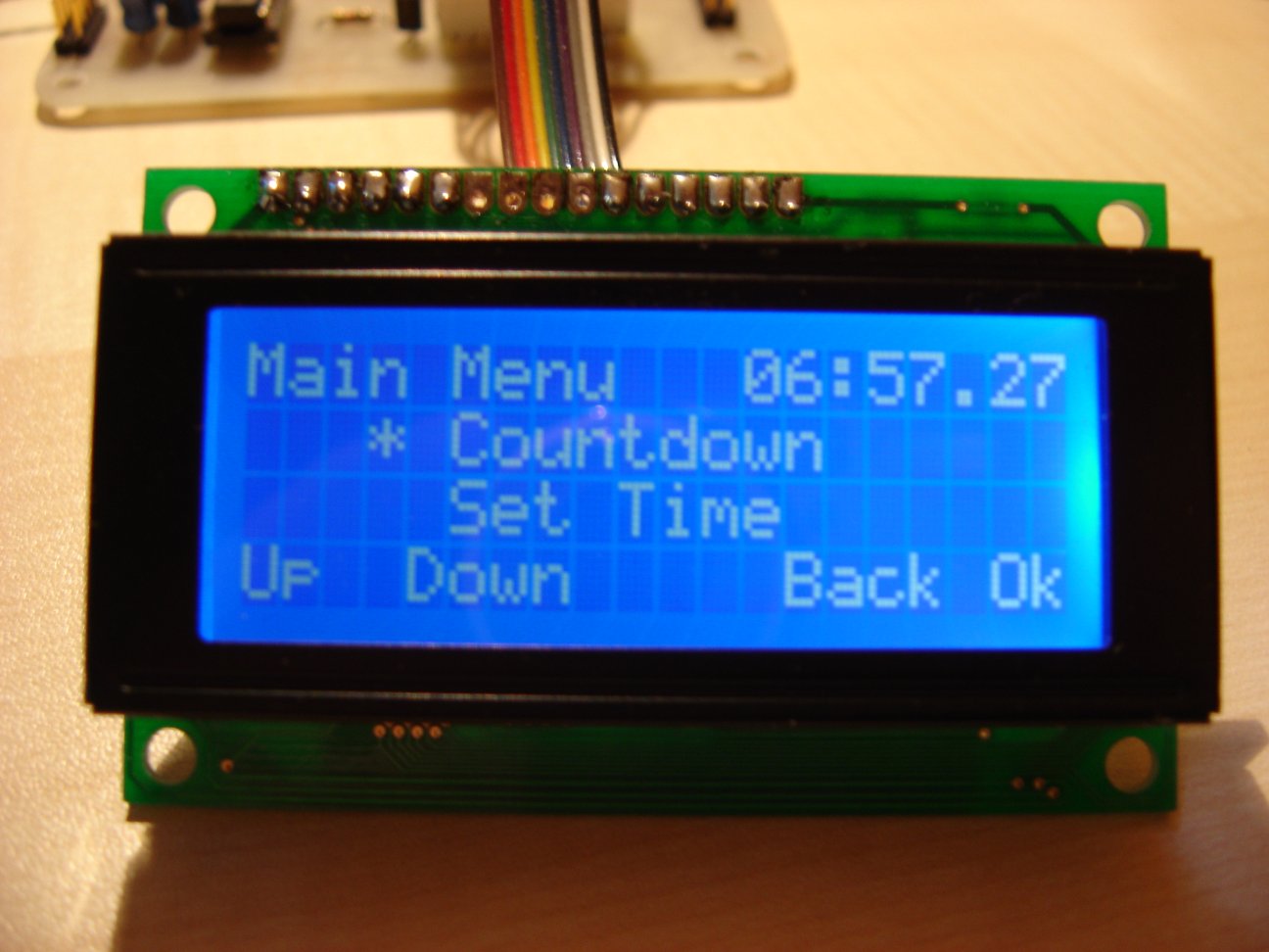
the main menu menu.jpg | 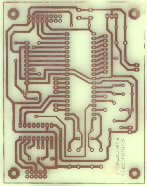
the pcb at first pcb-v1.jpg | 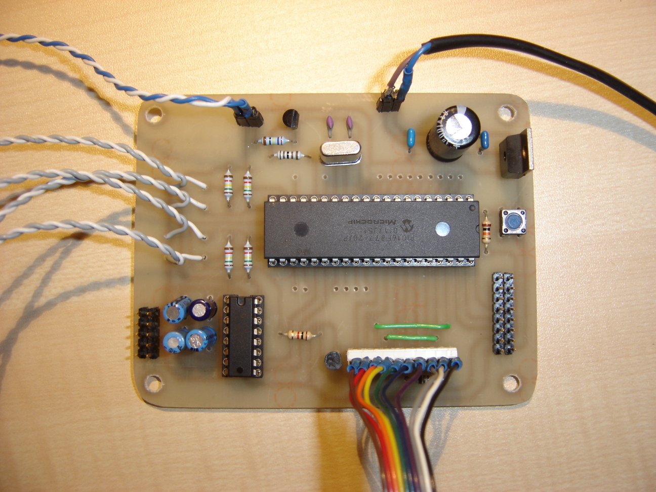
the pcb print.jpg |
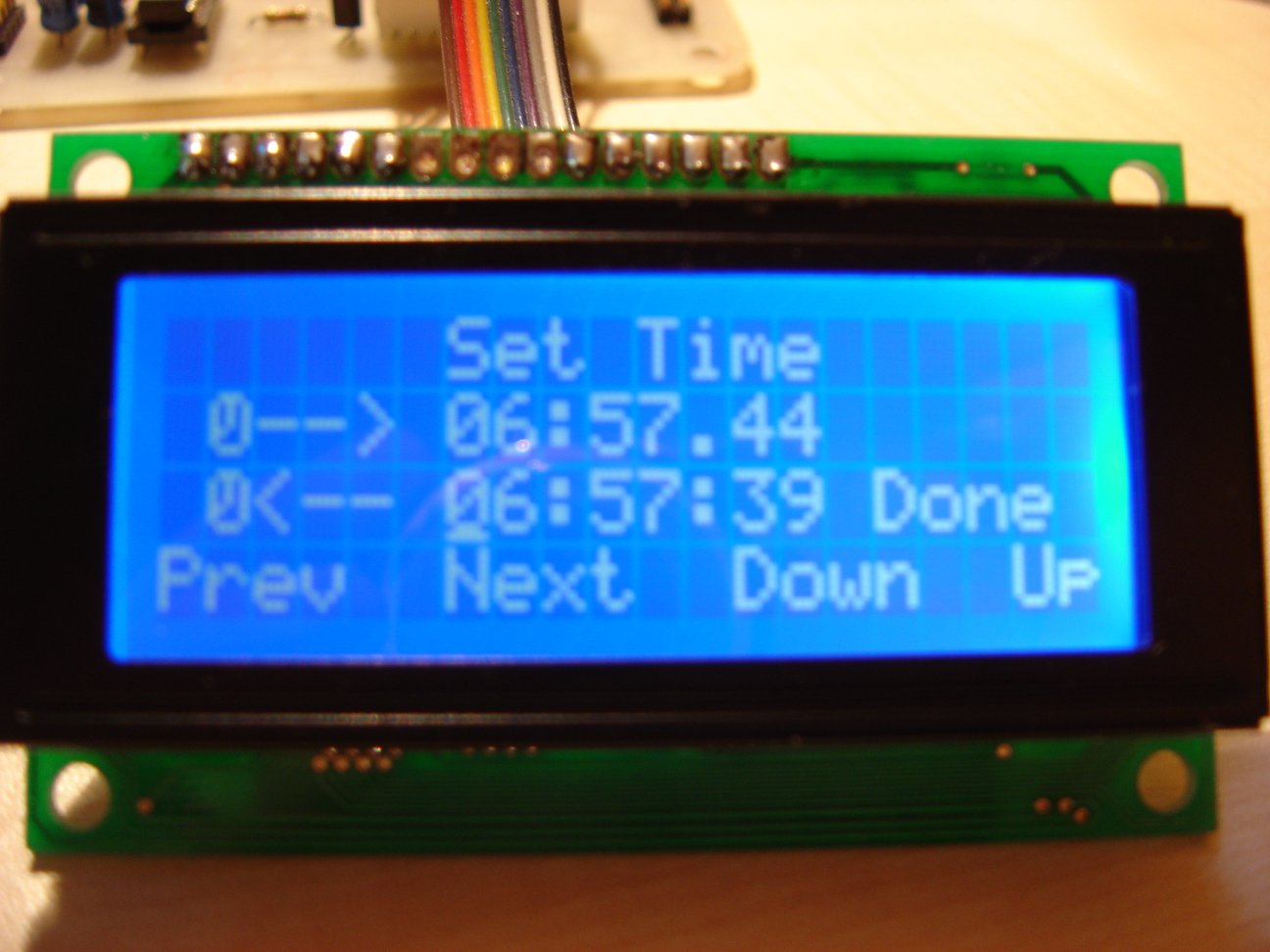
setting time... settime.jpg | 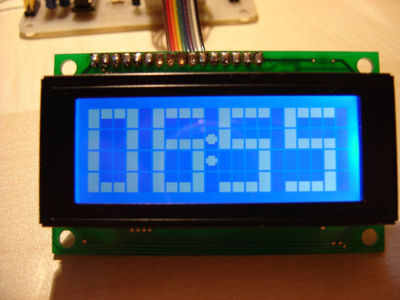
running... tijd.jpg |
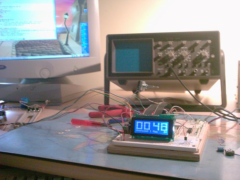
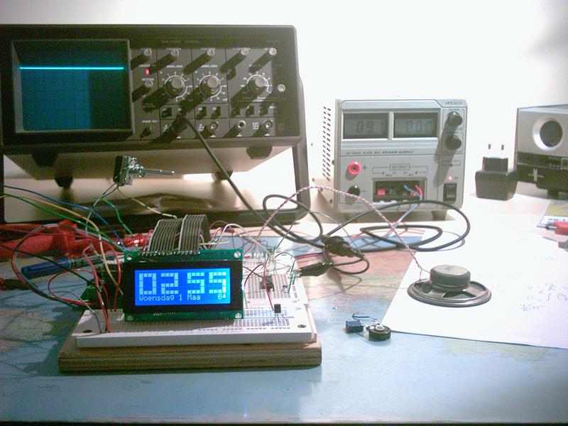
Lab setup
im000280.jpg | 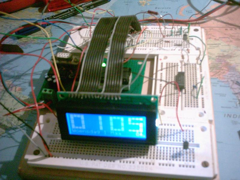
im000281.jpg | 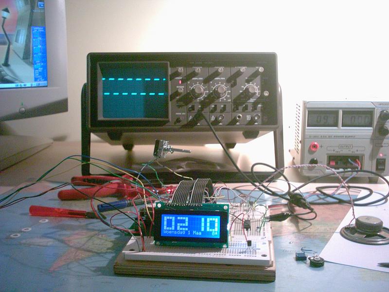
im000282.jpg | 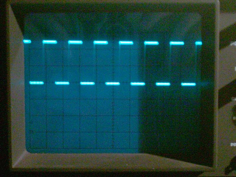
im000283.jpg | 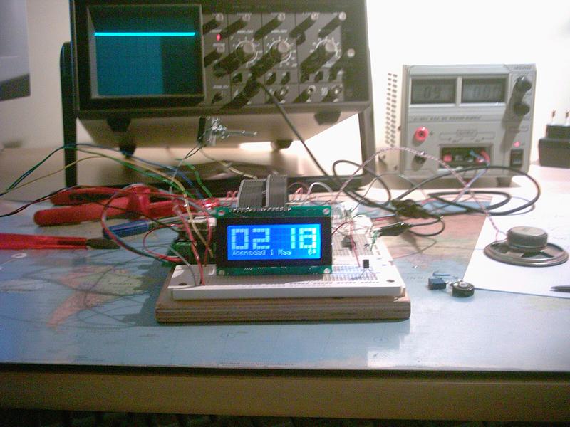
im000284.jpg | 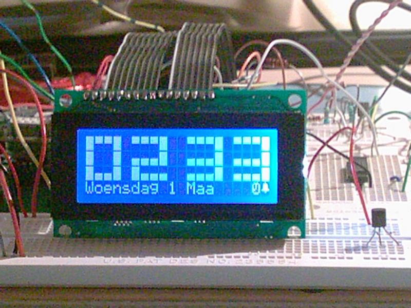
im000285.jpg |
im000286.jpg | 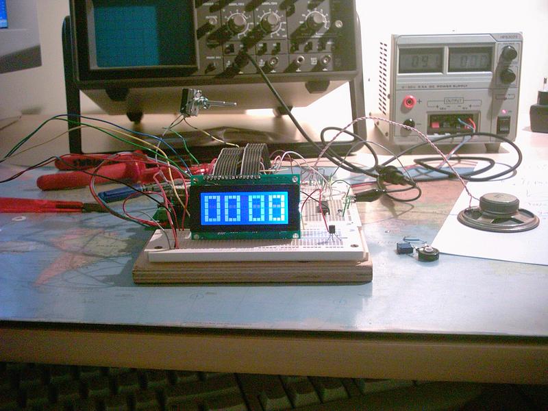
im000287.jpg | 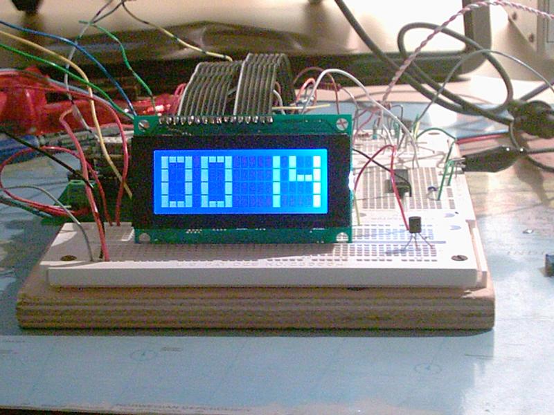
im000288.jpg | 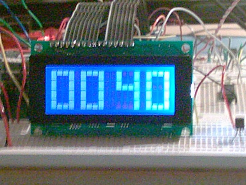
im000289.jpg | 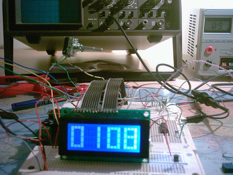
im000290.jpg | 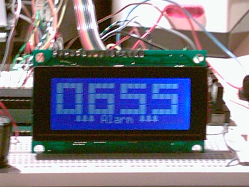
im000369.jpg |
im000381.jpg | 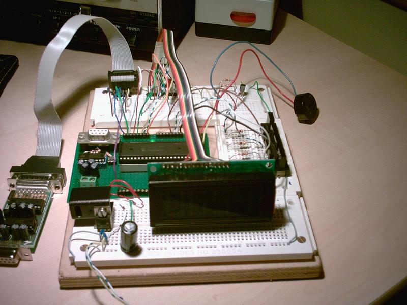
im000382.jpg | 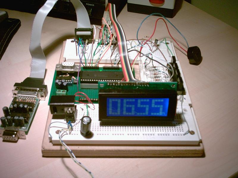
im000383.jpg | 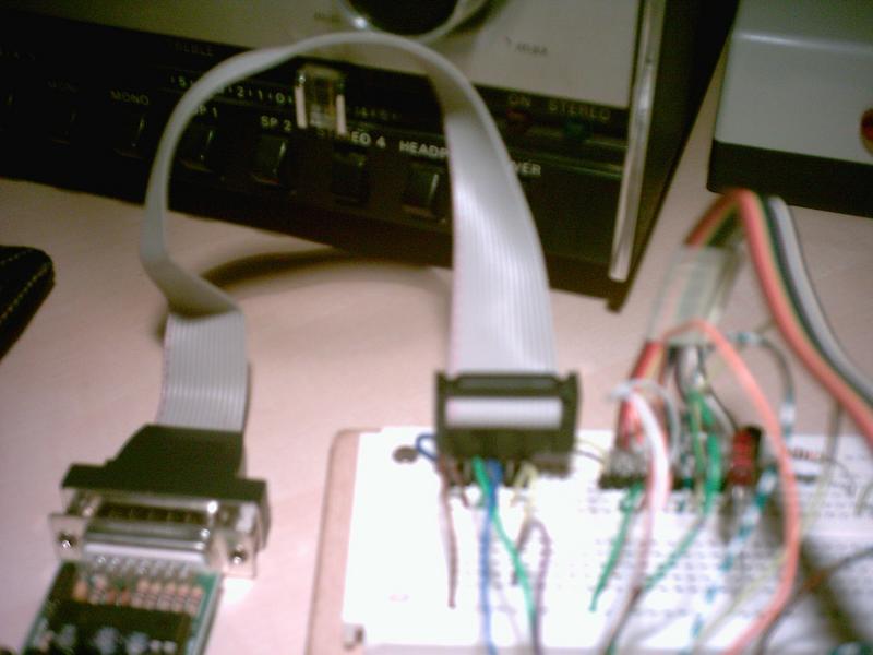
im000384.jpg | 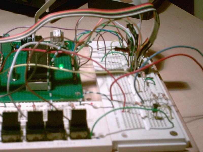
im000385.jpg | 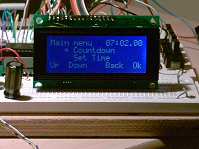
im000386.jpg |
im000387.jpg | 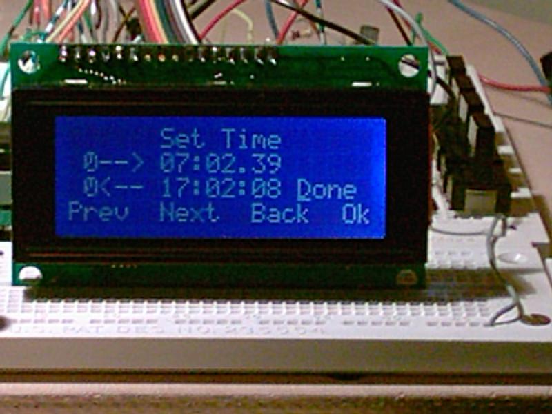
im000388.jpg | 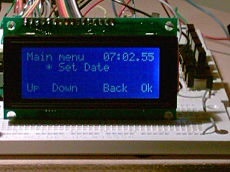
im000389.jpg | 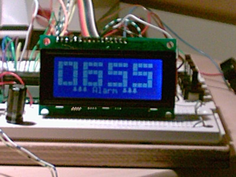
im000392.jpg | 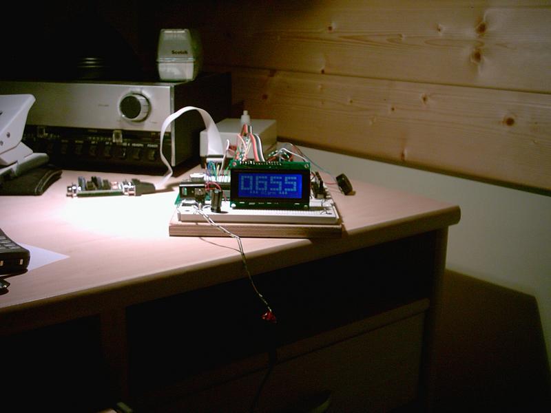
im000393.jpg | 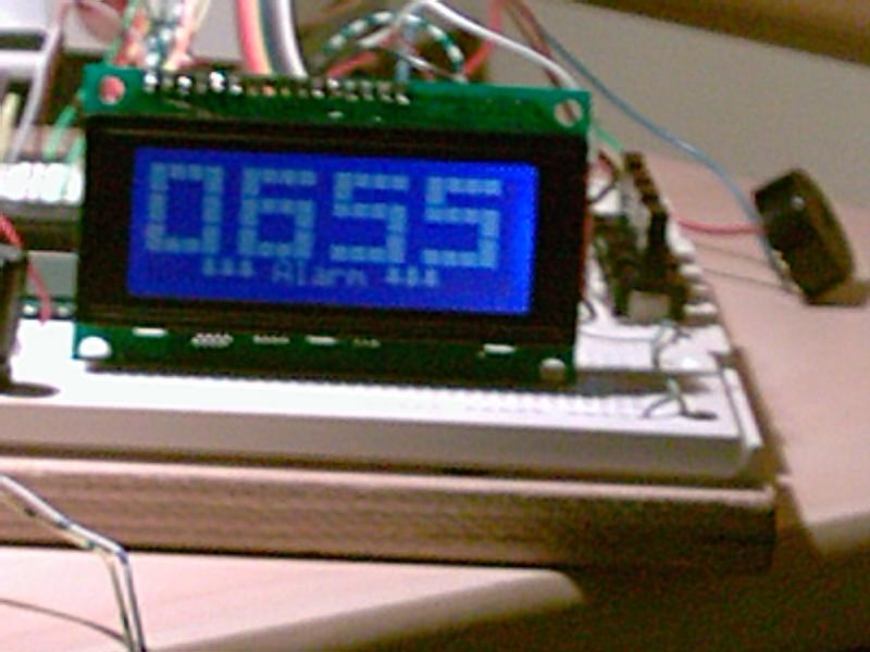
im000394.jpg |
Liked something? Worked on something similar? Let me know what you think on Mastodon!
You can direct-message me, or mention me @thouters@hsnl.social