JAL Programmable Logic Controller
When my brother was doing his last year of high-school in electromechanics, he came up with the idea of doing his final project using a homebuilt PLC instead of the usual Siemens stuff. I built the electronics and came up with a framework so he could easily implement his GRAFCET state machine for his part sorting robot for the PICMICRO in the JAL programming language.
This was long before Arduino, long before 'all the cool kids were doing it', and JAL was a free compiler for the affordable PIC microcontrollers. The Arduino of its days.
Overview
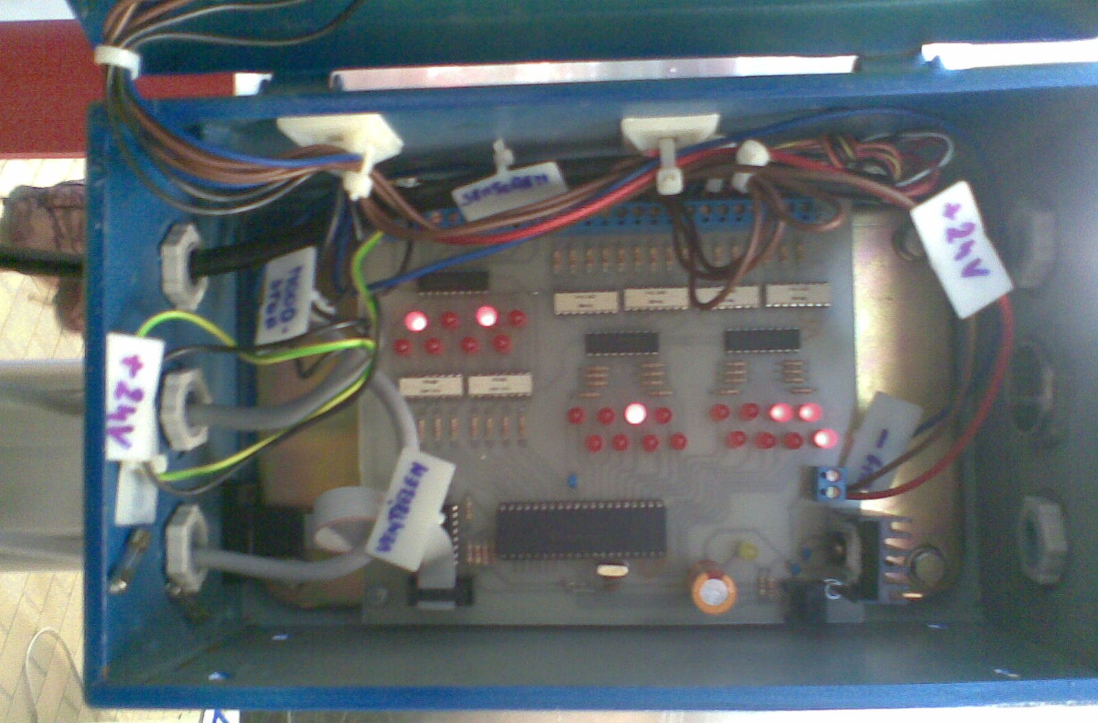
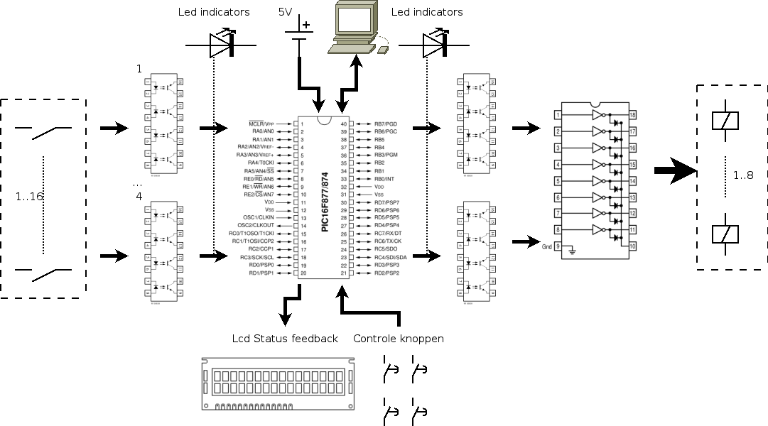
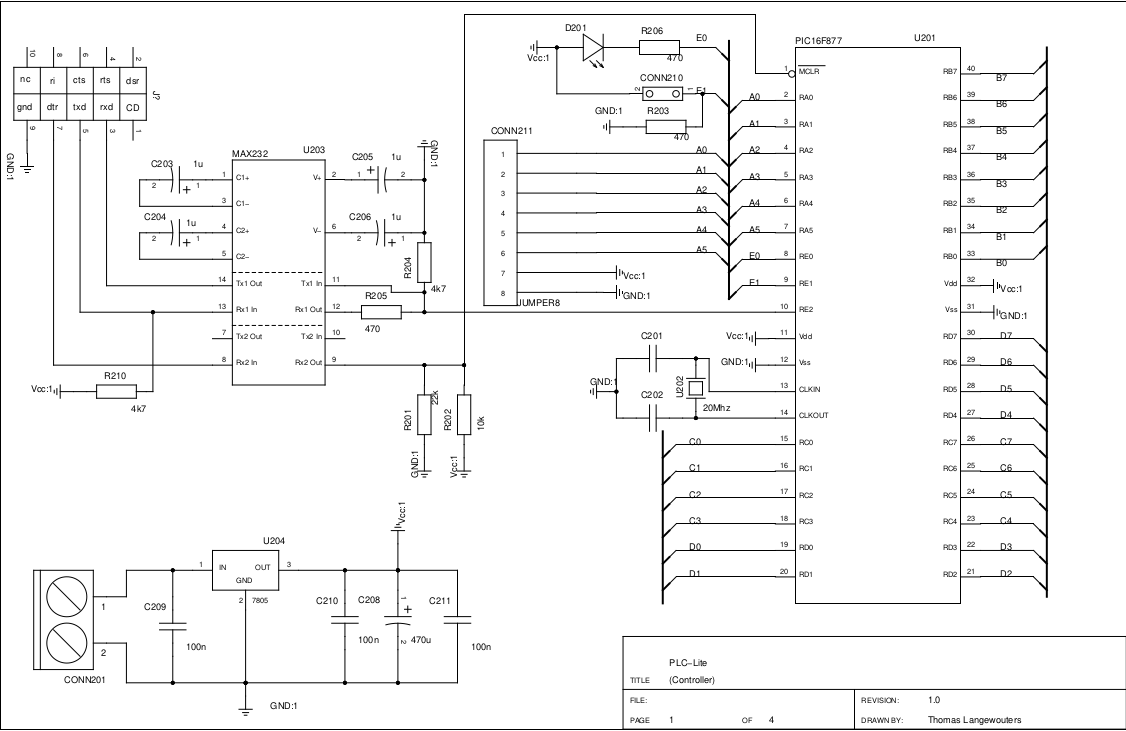
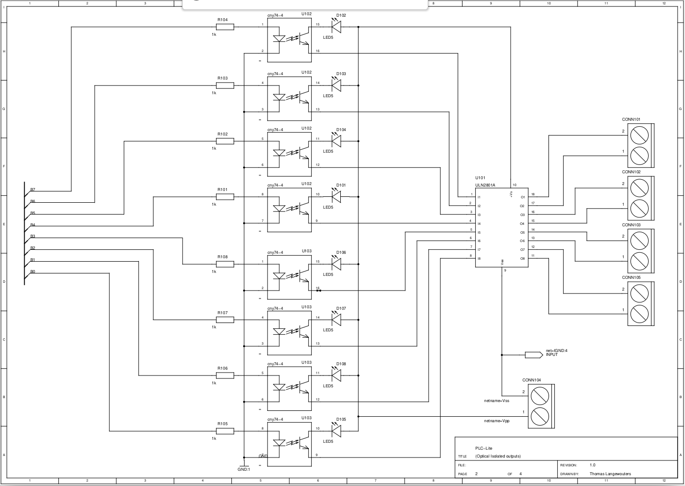
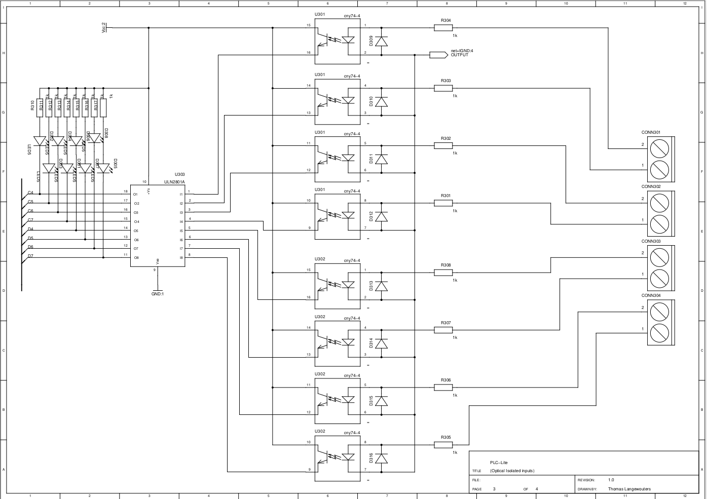
The circuit was pretty simple, a microcontroller with supporting components (serial port line shifter), 5V regulator and opto-isolators for I/O.
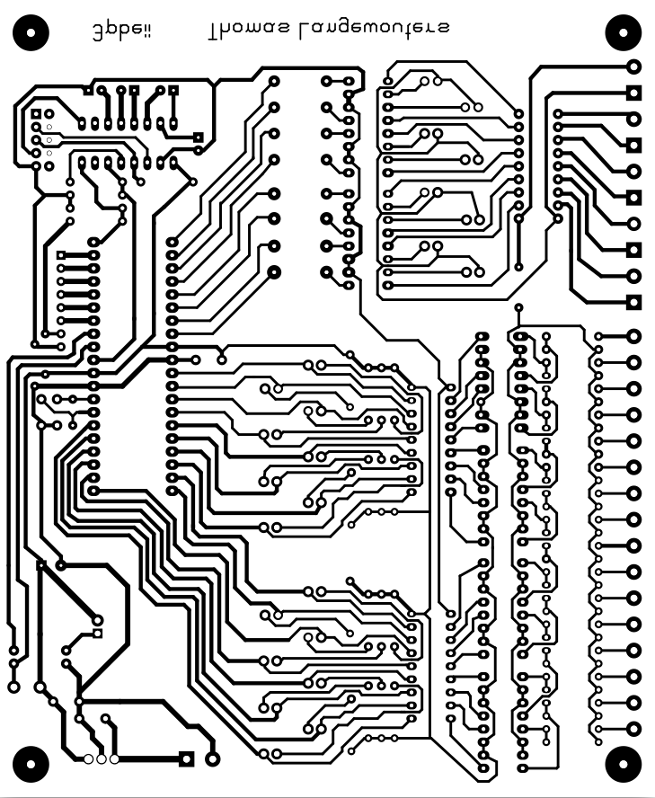
I had the PCB etched at my college which had a small electronics parts shop and PCB etching service.
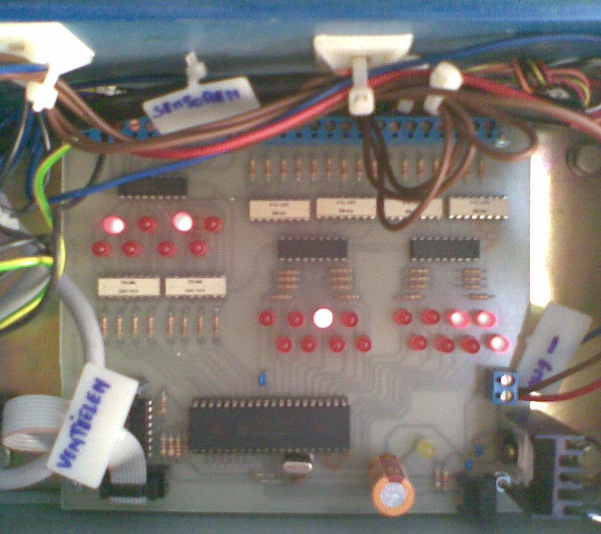
My brother mounted it in a circuit box on the robot.
Hardware
To learn something new, I used http://www.geda-project.org/ and did the schematic in gSchem and the PCB layout in PCB. I was used to Eagle at the time so the different keybindings and mouse behavior between schematic capture and PCB routing were a surprise to me.
Software
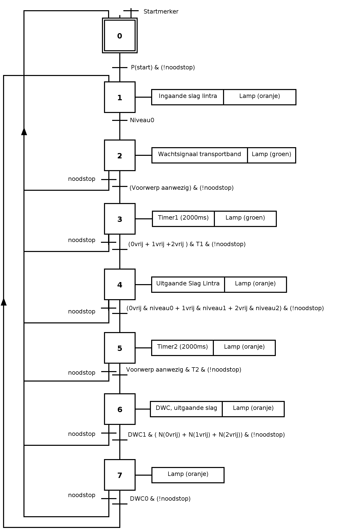
The state machine in GRAFCET notation was converted into JAL logic expressions and if statements.
Mainloop
Everything centers around a main loop:
include f877_20
include jlib
include p_states
include p_image
include p_timers
include th_timers
include th_symbols
disable_a_d_functions()
reload_init()
port_a_direction = all_output

forever loop
        process_input_image()
        include changes
        include outputs
        timerprocessing()
end loop
Timekeeping is done in an Interrupt service routine, and the timerprocessing() function will do some bottom-half processing.
Symbols
var volatile bit light1             is o1
var volatile bit light2             is o2
var volatile bit coil1              is o3
var volatile bit coil2              is o4
var volatile bit coil3              is o5
var volatile bit waitsignal         is o6

var volatile bit level0             is i1
var volatile bit level1             is i2
var volatile bit level2             is i3
var volatile bit obejct             is i4
var volatile bit shelve0occupied    is i5
var volatile bit shelve1occupied    is i6
var volatile bit shelve2occupied    is i7
var volatile bit dwc0               is i8
var volatile bit dwc1               is i9
var volatile bit emergencystop      is i10
var volatile bit start              is i11
var volatile bit start_edge         is i11_edge
var volatile bit specialflag        is i12
Process-input processing
procedure process_input_image is
    -- store input values from previous cycle
    -- old snapshot so to speak
    xi1_o = xi1
    xi2_o = xi2
    -- take snapshot of inputs to have consistent values
    -- during this cycle
    xi1 = ! xi1_port
    xi2 = ! xi2_port
    -- difference between old and new values
    xi1_e = xi1 ^ xi1_o
    xi2_e = xi2 ^ xi2_o
    -- write output image to the output port
    xo_port = xo
end procedure
State changes
if ( step0
    & start_edge
    & start
    & emergencystop
) then
     step0 = off
     step1 = on
end if

if ( step1
    & level0
) then
    step1 = off
    step2 = on
end if
Output
-- specify in which states the timer is active
t1_enabled = state1

-- activate an output in certain states
-- use an OR operator instead of AND to activate it in multiple states like this:
-- siren = state9 | state23
-- the reasoning behind this is
-- 'activate output when state X is acive OR state Y'
light1 = step1
light2 = step0

-- light3 = button
Timers
To offer an easy way to add delays to the state machine, a mode and value variable are used.
-- set t1_mode to seconds or milliseconds, exmaple:
-- t1_mode = seconds
-- t2_mode = milliseconds

t1_mode = seconds
t1_value = 5

t2_mode = milliseconds
t2_value = 200
Liked something? Worked on something similar? Let me know what you think on Mastodon!
You can direct-message me, or mention me @thouters@hsnl.social