Central Heating sensor manipulation
We used to have a gas-powered central heating system that had no external controls other than radiator valves. It had a sun-exposed exterior temperature sensor on the west side of the house that caused it to refuse to heat in the evening.
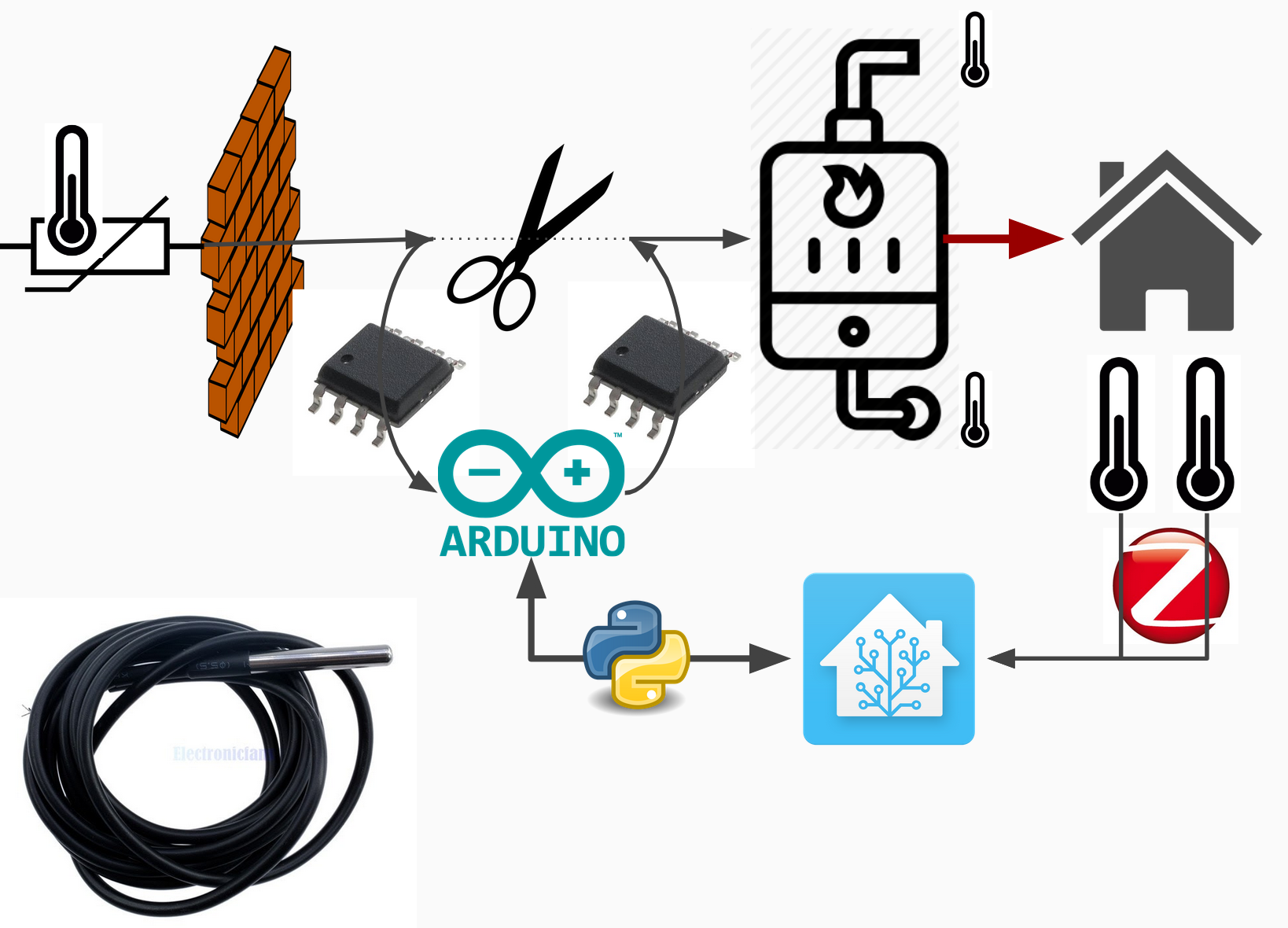
I wanted to fix the issue and control it via Home Assistant, and since only the newer models had bus control, I resorted to manipulate the outside sensor readings and designed a man-in-the-middle device.
Introduction
The central heater was meant to be always on, even though no floor heating was installed. It had a built-in clock which it used to lower the water temperature a bit during the night.
The system did not have thermostatic valves on the radiators, but with minor tweaking to its PID values produced comfortable temperatures.
The house did not have a north-side to install the exterior temperature sensor onto, so it was mounted on the west side. My first idea was to replace that temperature dependent resistor with a digitally controlled resistor, and feed it the temperature value from a wireless thermometer placed in the backyard shade.
Hardware
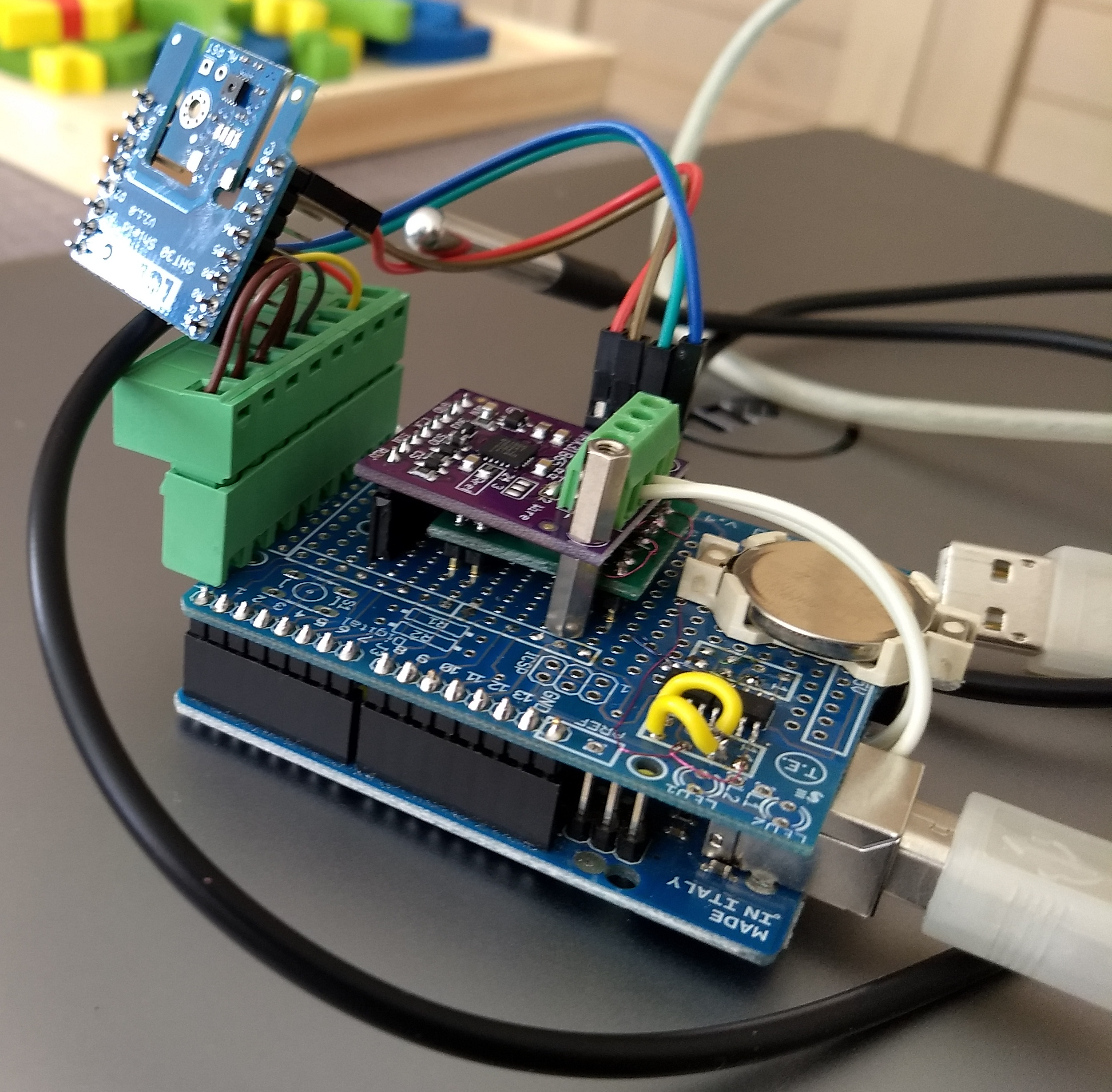
- Arduino Uno based interface board
- perforated pc-board based point-to-point wired prototype
- MAX31865 temperature dependent resistor interface
- MCPxxx SPI digital potentiometers, optically isolated and powered by CR2032 battery
- Dallas one-wire temperature sensors on the water-in and -out feeds.
The Arduino runs a simple mainloop program I compiled and uploaded using platformio.
It employed a simple ASCII based request/response stream protocol to trigger I/O actions.
- Set the digital potentiometer values
- return the resistance reading of the outside thermometer.
lib_deps =
    Adafruit MAX31865 library
    https://github.com/PaulStoffregen/OneWire.git
    https://github.com/milesburton/Arduino-Temperature-Control-Library
Software
I created a python daemon that I ran in a docker container using systemd. I used Paho-MQTT and tried to leverage asyncio.
I also used python3-serial to talk to the Arduino, and the UliEngineering module to convert the resistance value to temperature.
I created a helper tool to perform calibration of the digital potentiometers when the device was wired in a 'loopback' mode. It obtained a MAX31865 resistance reading for each of the possible potentiometer values. The values were dumped in a text file and used to translate a resistance value to the best matching potentiometer setting.
Home assistant integration
The python daemon exposed the temperatures on MQTT topics, and listened on a MQTT topic for the outside temperature it should emulate towards the heater.
MQTT template sensors were used to bring this project into my Home Assistant instance!
Liked something? Worked on something similar? Let me know what you think on Mastodon!
You can direct-message me, or mention me @thouters@hsnl.social