Heat Canon (Salamander heater) controller repair
In the winter of 2016, I was asked to repair a controller board for a heater. The heater is pretty scary, it burns fuel and blows exhaust and hot air out of what looks like a canon. It has some interesting mechatronics; a fuel valve, an ignition coil, and a fan. It has a flame detection sensor input as well, as a safety feature. I succeeded at repairing the board, but had to write the controller software from scratch.
Electronics
After inspecting the board and hooking it up to mains voltage, it became clear that the microcontroller on the board was dead, it was pulling more than 150mA. Possibly killed by ESD, heat or some flyback current from one of the coils it drives.
The microcontroller is powered via a capacitive dropper (series capacitor/resistor) and a zener diode, which means some precautions must be made when testing, since all electronics is connected to live mains.
Looking at the top of the board, the original microcontroller is a cheap HT48R05A, a one-time-programmable microcontroller. I considered replacing it with something I had around. From a selection of 8051, AVR and PICMICRO devices, a PIC16F84 I bought when I was still a teenager was the best physical fit.
Since the PIC has a different pinout than the Holtek, some circuit adjustments are necessary, these were done using knife and bodge-wire.
I also replaced the original resonator with a RC oscillator configuration, the 16F84 does not have an internal RC like the 16F628 does, and putting in a crystal was physically a bad fit.
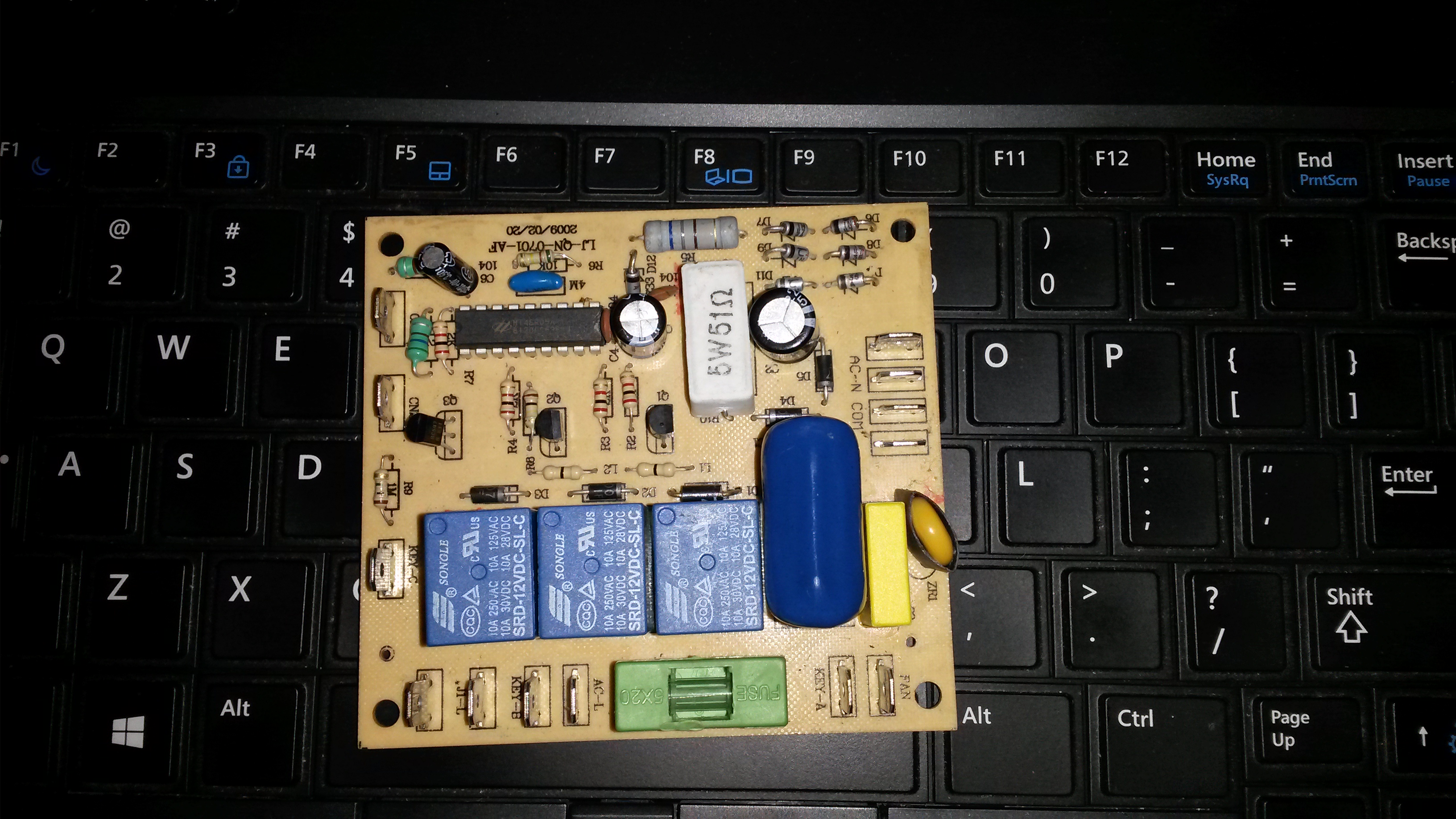
Unmodified top of the board
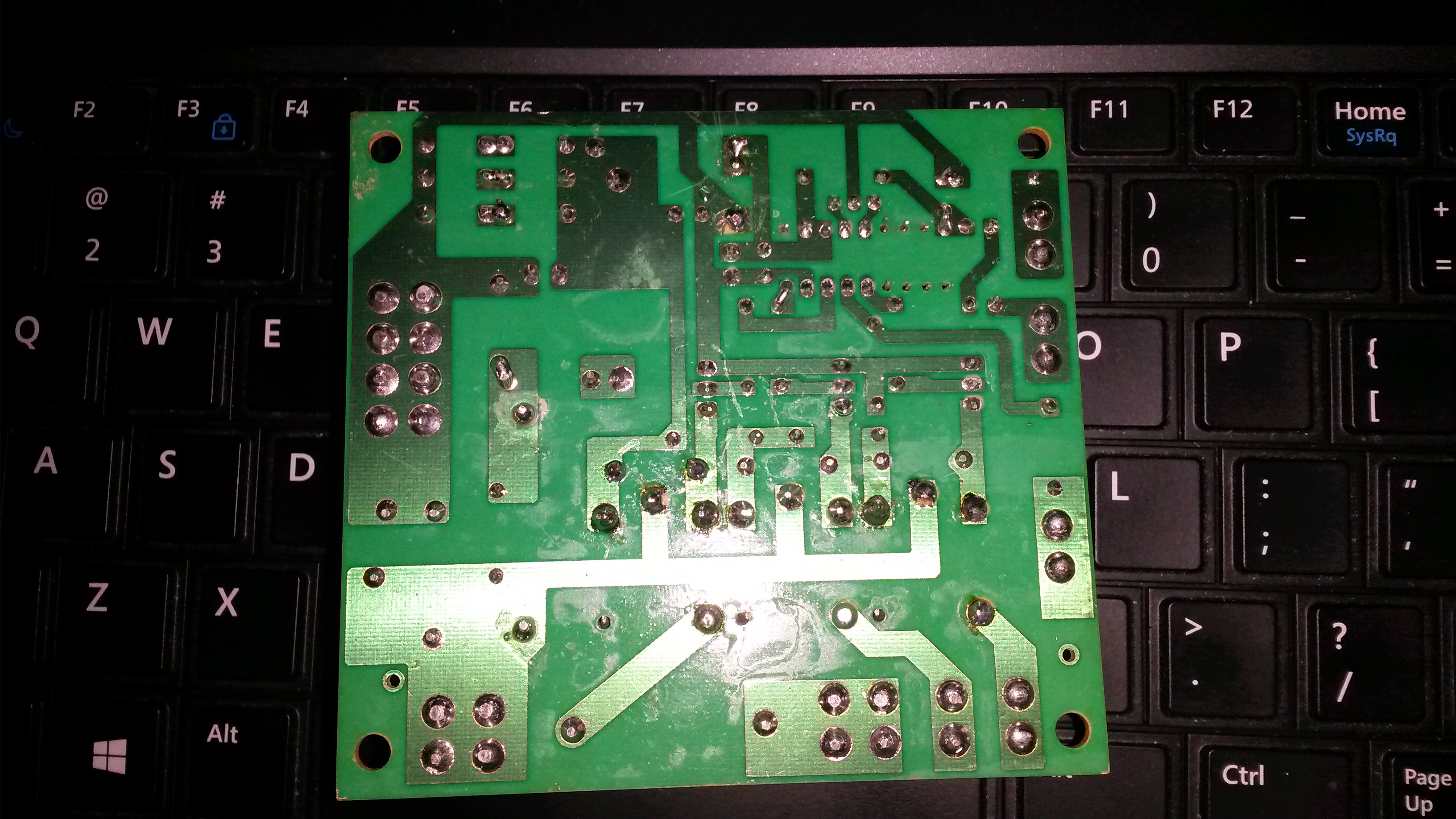
Unmodified back of the board
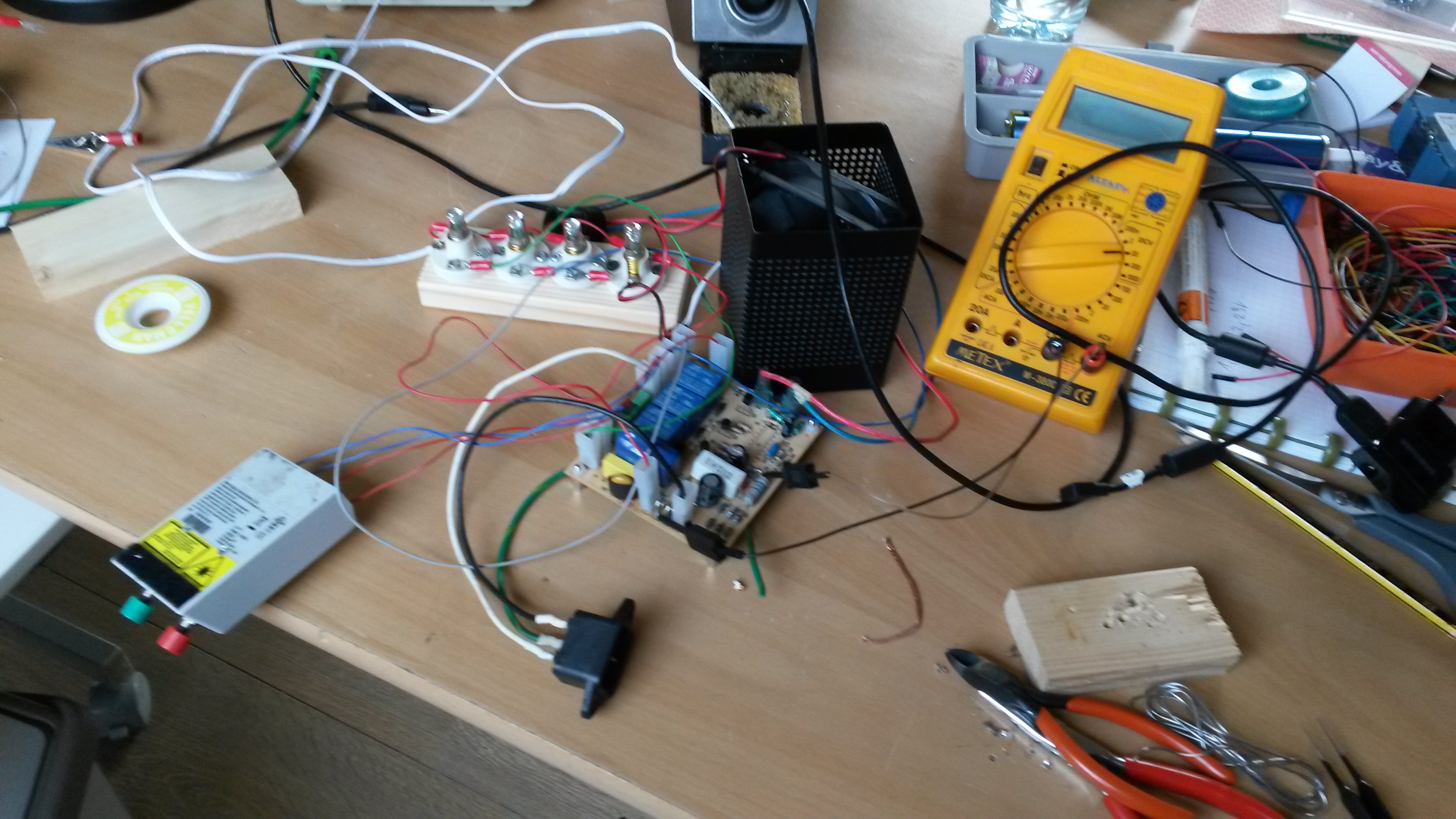
High-voltage testing setup
Software
I considered writing the new software using JAL, the pascal-like programming language I used when I was a teenager. However, I had been wanting to try SDCC for an embedded project for a while, so I gave that a try. The pic14 port proved usable, so I wrote this in C.
I dug up my old WISP (Wouter's in system programmer, from www.voti.nl), and it still worked fine.
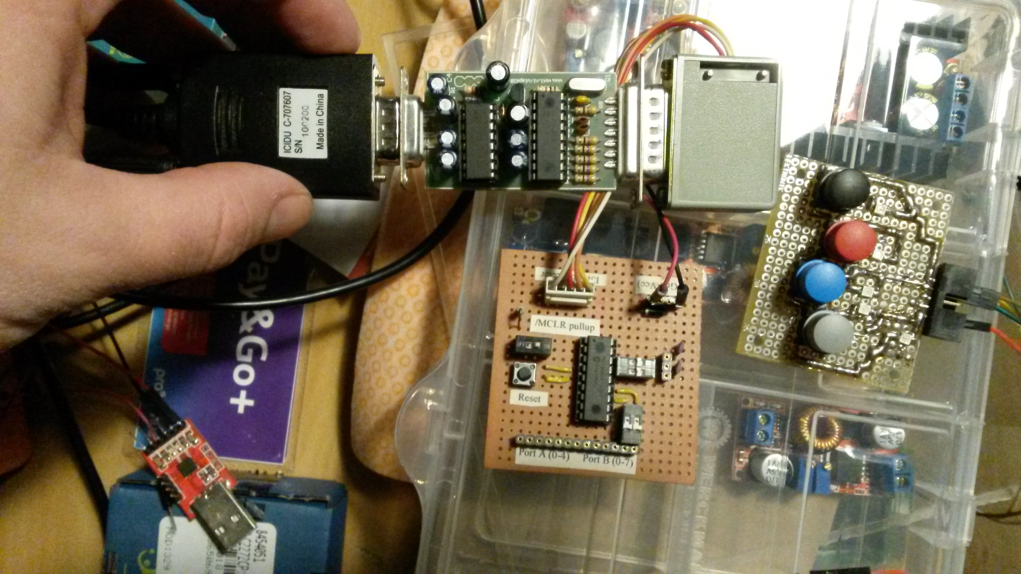
WISP PIC Programmer
I had a description about how the device was meant to operate, and from that composed a state chart.
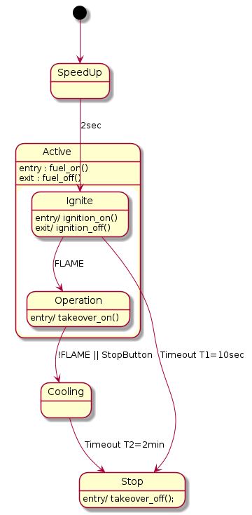
Outdated state diagram, I made a flowchart on paper.
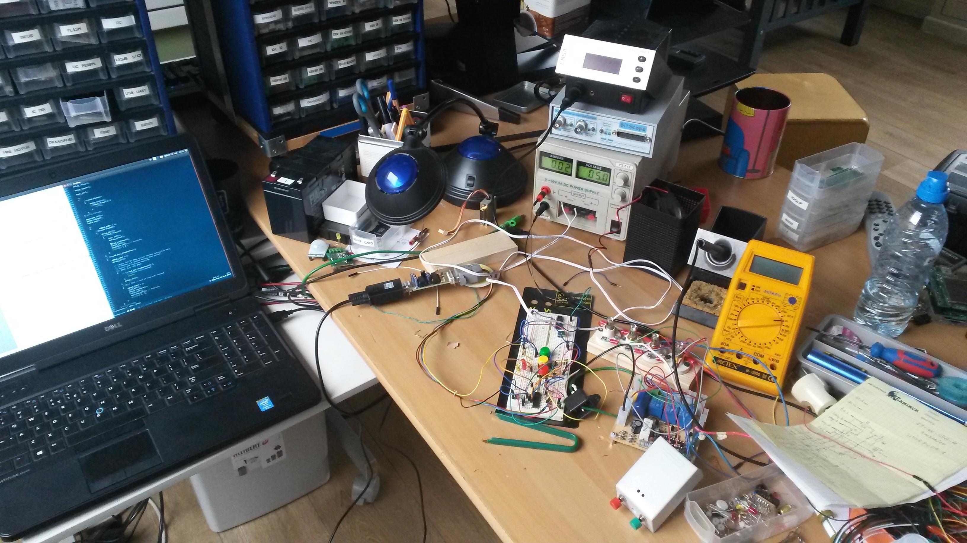
I first wrote basic I/O functions and tested them on a breadboard with LEDs and switches, powered by a lab supply.
Then I converted the flowchart into a classical, blocking main loop style program (no event loops for simple stuff like this...)
Once I was confident that everything was OK, I moved the controller chip to the IC socket I put on the board.
Software development setup
I put the firmware on GitHub in case someone is interested. However I discourage using this for repairs.
Final result
Here is a demo of the fixed hardware being tested with neon bulbs instead of the heater's actuators. You can see the flame detection LDR (Light dependent resistor) functions, and will initiate the fail safe when the flame disappears (when I hold it down to the table).
Liked something? Worked on something similar? Let me know what you think on Mastodon!
You can direct-message me, or mention me @thouters@hsnl.social