Rainwatertank Level Sensor
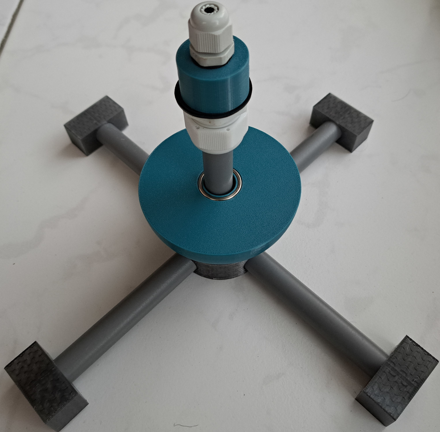
Mechanical sensor parts assembled with a very short sensor tube to fit the picture.
This project combines electronics, water and creating something from scratch. I couldn't resist designing my own reed switch array water level sensor.
This kind of sensor has a floating part with a magnet moving up and down a sensor tube.
It's not an off the shelve solution to sensing water levels, buying a water pressure sensor or an ultrasonic level sensor would probably be easier, but DIY is fun!
My goal was to do some electronics and 3D design, 3D print, experiment and get a circuit board fabricated. I'd build a sensor using easily obtainable parts whenever possible. The electronics should be easy to build at home.
I will use it to monitor and log the water level in Home Assistant. Getting to automate the adding of a minimal amount of tap water to the tank during the summer will be a useful feature.
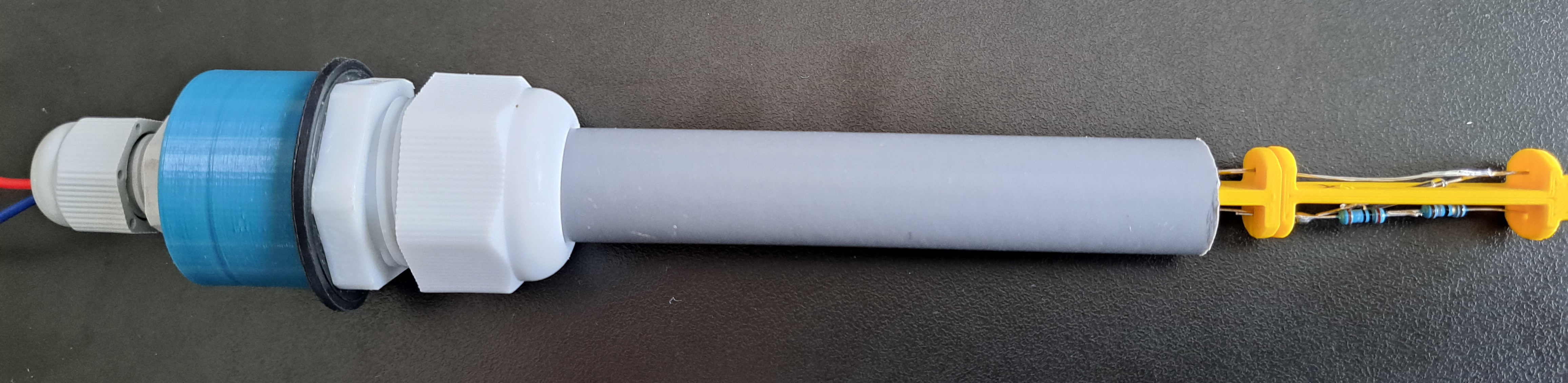
completed sensor
Other design goals I came up with include:
- The working range of the water level shall be between 10cm and 1m50.
- I will use as many components as possible that I have on hand in my workshop.
- The sensor shall output a signal at all times when powered.
- There shall be no programmable electronics in the sensor.
- Lean towards using industrial interface standards.
So I ordered some reed magnet switches and started prototyping...
Principle
A reed chain level sensor is a large sliding variable resistor really. However, instead of acting continuous like a potentiometer, its resistance can only change by a constant step each time, one for each reed switch in it.
Water level sensor prototype with exposed reed chain
The reed chain level sensor separates electronics from the liquid environment by enclosing them in a tube. The reed switches are operated via a magnet that can slide across the tube.
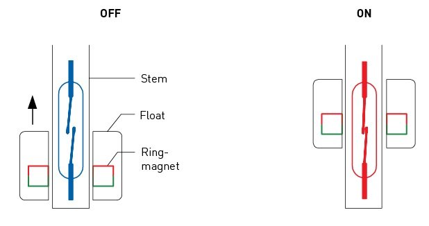
Sensing a one dimensional position with a reed switch
To have a continuous output signal, I need to have at least one of the reed switches closed when the floater is around the tube. This means the choice of reed switch spacing and magnet field strength will be closing two switches when the floater is crossing over.
Closing at least one reed switch is no issue using neodymium magnets.
The circuit has to be designed in a way that allows two switches to be closed at the same time.
If we configure the reed chain as a multi-resistor voltage divider of which each reed switch couples one of the nodes to an output, we would be shorting out a resistor. (However, shorting out a relatively small piece of the chain could be acceptable)
So I considered two possible chain configurations.
Another thing to keep in mind is hysteresis, when the magnet moves across the shaft, the reed switch will return to open on a point lower than it closed close it since the magnetic circuit will require less magnetic flux to hold than to close. This will decrease precision with regular rainfall.
Reed chain configuration
Three terminal variable resistor
If we apply a voltage over a resistor chain with reed switches on each junction, we get a voltage representing the magnet's relative position at the reed switch normally open output.
If we connect the reed switches together, we can sample this position.
Since one of my design goals was to have at least one reed activated, there will be overlap. To avoid shorting out a resistor and increasing precision, we can interleave the reed switch connections to two outputs.
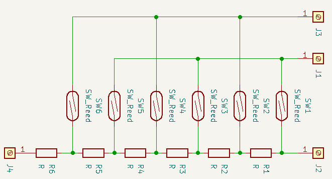
Since this implies a more complicated reed chain and more complicated electronics, I moved on to investigate a two terminal variable resistor.
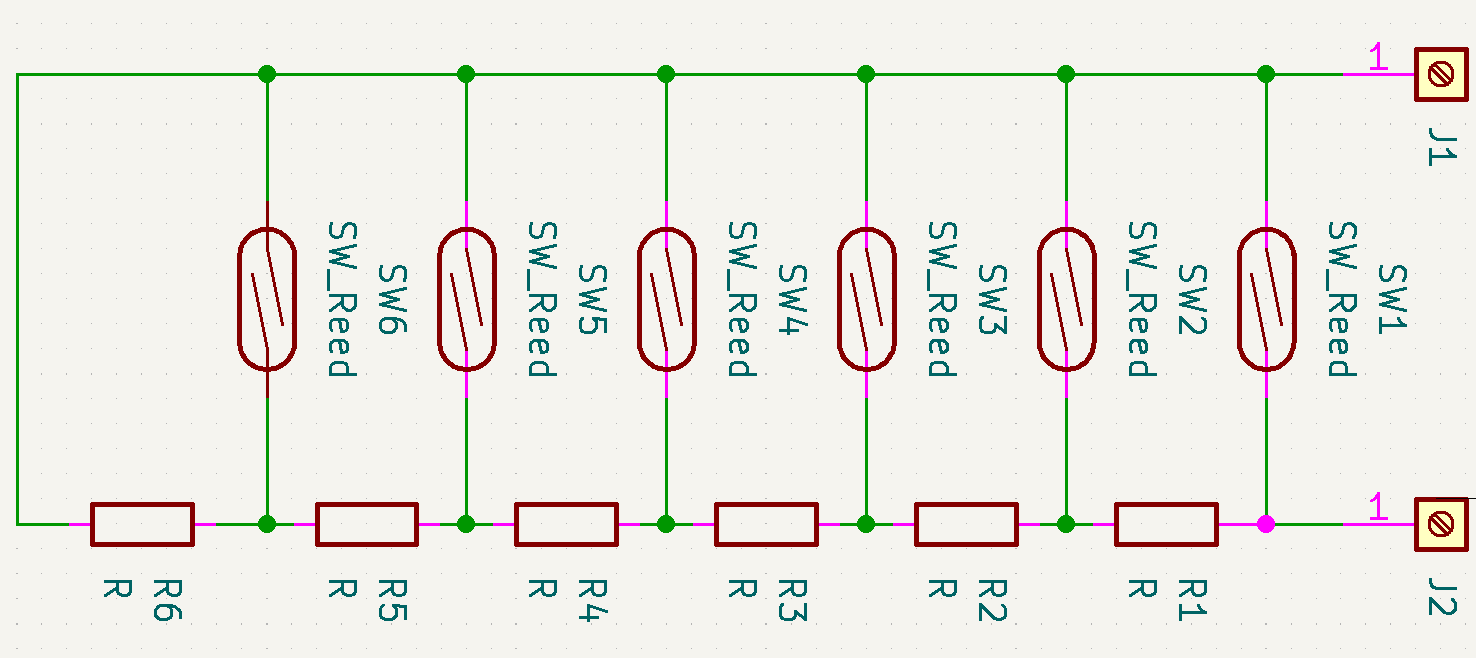
Two terminal variable resistor
This is a very simple setup that will output a resistance between 0 ohm and the series resistance of all resistors.
Electronics
Sensor interface
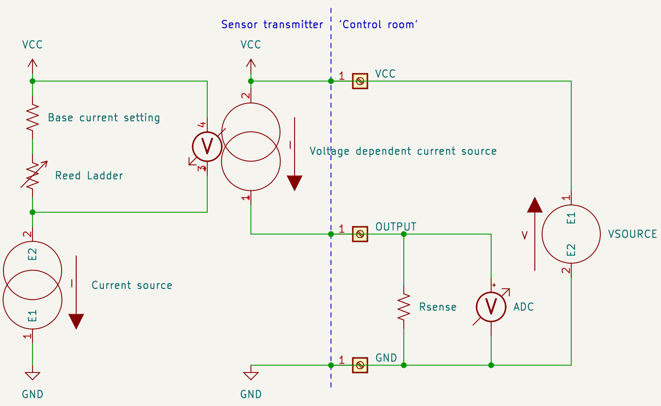
I decided to design a three-wire 4-20mA current loop converter with a current sourcing output.
This is an industry standard interface for sensors that has been around for many decades. A 3-wire sensor is connected via three wires and the nature of the constant current output signal compensates for voltage drops across the wires and junctions along the factory floor.
It's fairly easy to understand. To use a three wire current loop sensor:
- You feed the device a supply voltage over it's supply wire and ground wire
- The device outputs a current between its output pin and its ground wire.
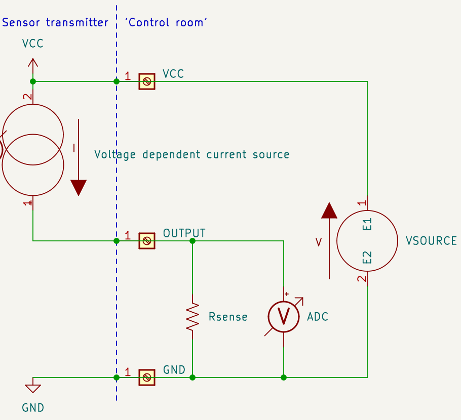
This makes it easy to interface with an ADC that has a common ground with the device, The constant current signal can be converted to a constant voltage by adding a resistor (Rsense). The value of the resistor determines the voltage range you will get. To convert the maximum output current of 20mA to a 3v3 signal, you can use ohm's law to find the resistor to use; R=U/I = 3.3/0.02 = 165 Ohm.
Design parameters
My sensor will output 4-20mA. This means the working range of 16mA will need to be divided over a number of reed switches. I figured 40 switches over the 1.5 meters would be a workable accuracy, this number will always a trade of between
- Having build and solder N resistor+reed switch steps by hand
- Resistor tolerances of 1% making too small steps useless.
- combining resistors of preferred numbers series (see E-series values) to closely match calculated values
Possible circuits
To realize a circuit with a constant current output I considered a simple zener diode + common emitter (transistor) current source as well as using a three terminal voltage regulator like a 78L05. The first one would be sensitive to temperature changes and in the latter the quiescence current would complicate calculations.
Since I had TL431 voltage references (on reel) that can be used as accurate 2.5V shunting voltage regulators, I opted to use those instead.
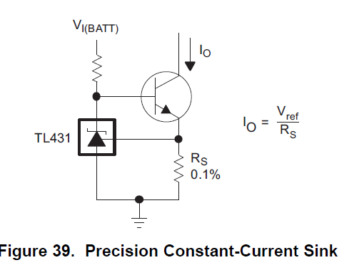
If I would use the TL431 as current source with my reed level sensor variable resistor, 2.5V at 16mA would mean the full scale of the resistor ladder would be 2.5V/0.016A = 156.25 Ohms. This low resistance would have to be divided up into even lower resistors in a ladder. That would be inconvenient (However I think I could work around this if I were to feed the TL431's vref feedback loop via a voltage divider.)
The main drawback with this circuit is that the resistance to current conversion would not be linear, since current = voltage / resistance and the voltage is of course constant.
My circuit: operation
To turn the reed ladder's resistance into a linear current, I added an intermediate step.
The TL431 voltage reference U1 is turned into a fixed current source by adding a transistor Q1. U1 will sink the right amount of current to have Q1's emitter pin be at 2.5V.
The fact that The voltage over R1+R6 will be 2.5V means the current through it will be I=U/R = 2.5/1.25k = 2mA.
I'll create a transconductance amplifier, which is a current sourcing current-source controlled by the voltage drop over R2 + R5.
R5 will set the minimum output current (4mA) of the circuit by providing a minimum voltage for the transconductance amplifier formed by U2A. U2A will mirror the voltage over R2+R5 over R4, (the significant part of) the current going through R4 will also flow to the circuit output, which will make the circuit output behave as a current source.
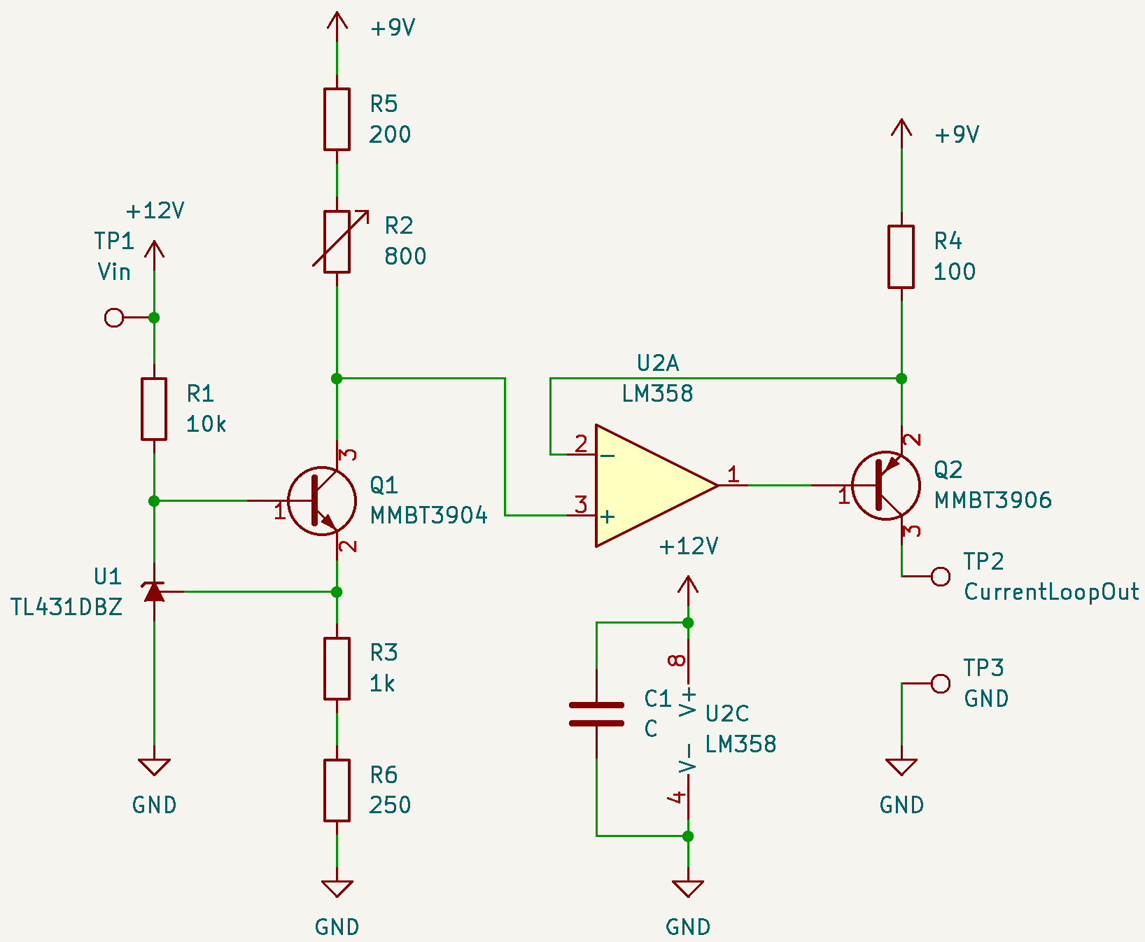
One design boundary to consider is the opamp can ony operate a few volts from its power supply rail. Since the transconductance amplifier configuration is working against the positive supply rail, I used the second opamp to create a voltage supply rail that is only a 2/3 fraction of Vin. This only costs an extra transistor since the LM358 has two opamps in the package.
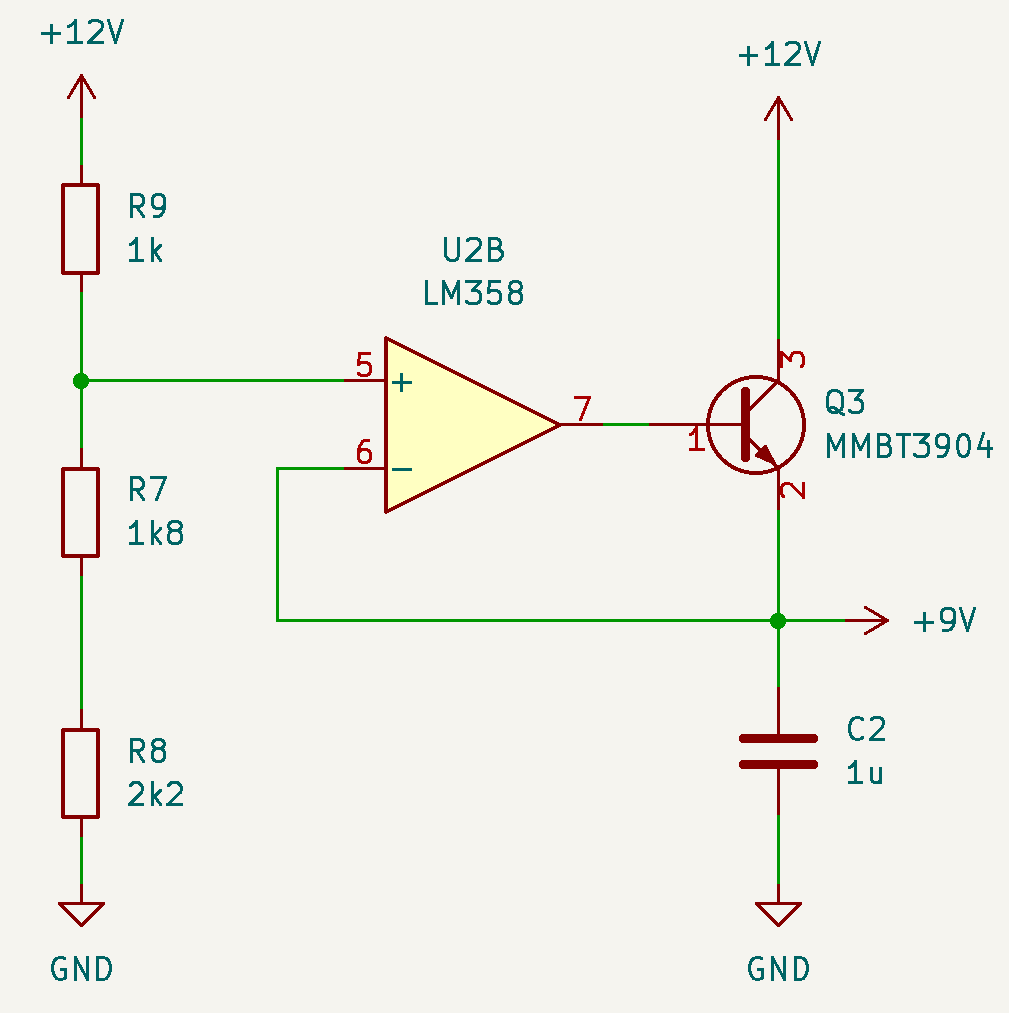
using an opamp to create a voltage lower than Vin.
After prototyping the circuit on perfboard, it was easily turned into a simple PCB and exported with KiCAD to something JLCPCB can work with.
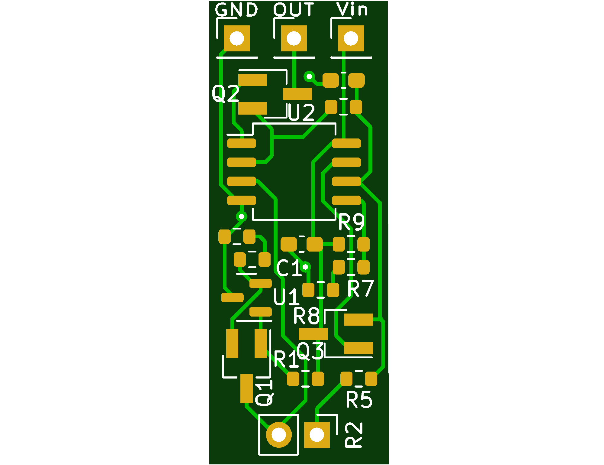
first revision PCB
You can find the design files in my resistance_to_currentloop github repository
Mechanics
I wanted to use items from the hardware store as well as 3D printed items.
Reed ladder
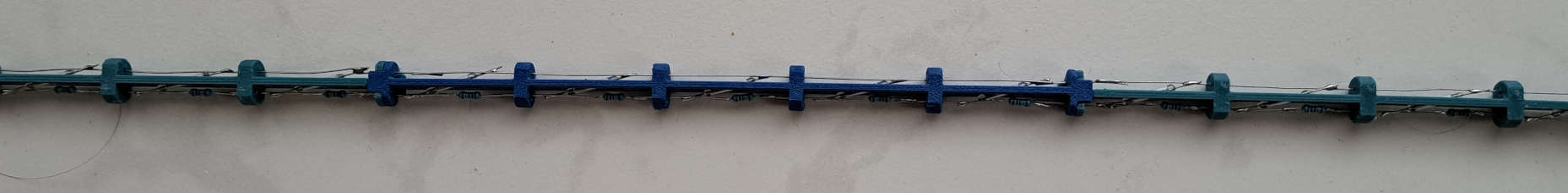
The reed ladder circuit is hand soldered and supported by 3D printed fixtures:
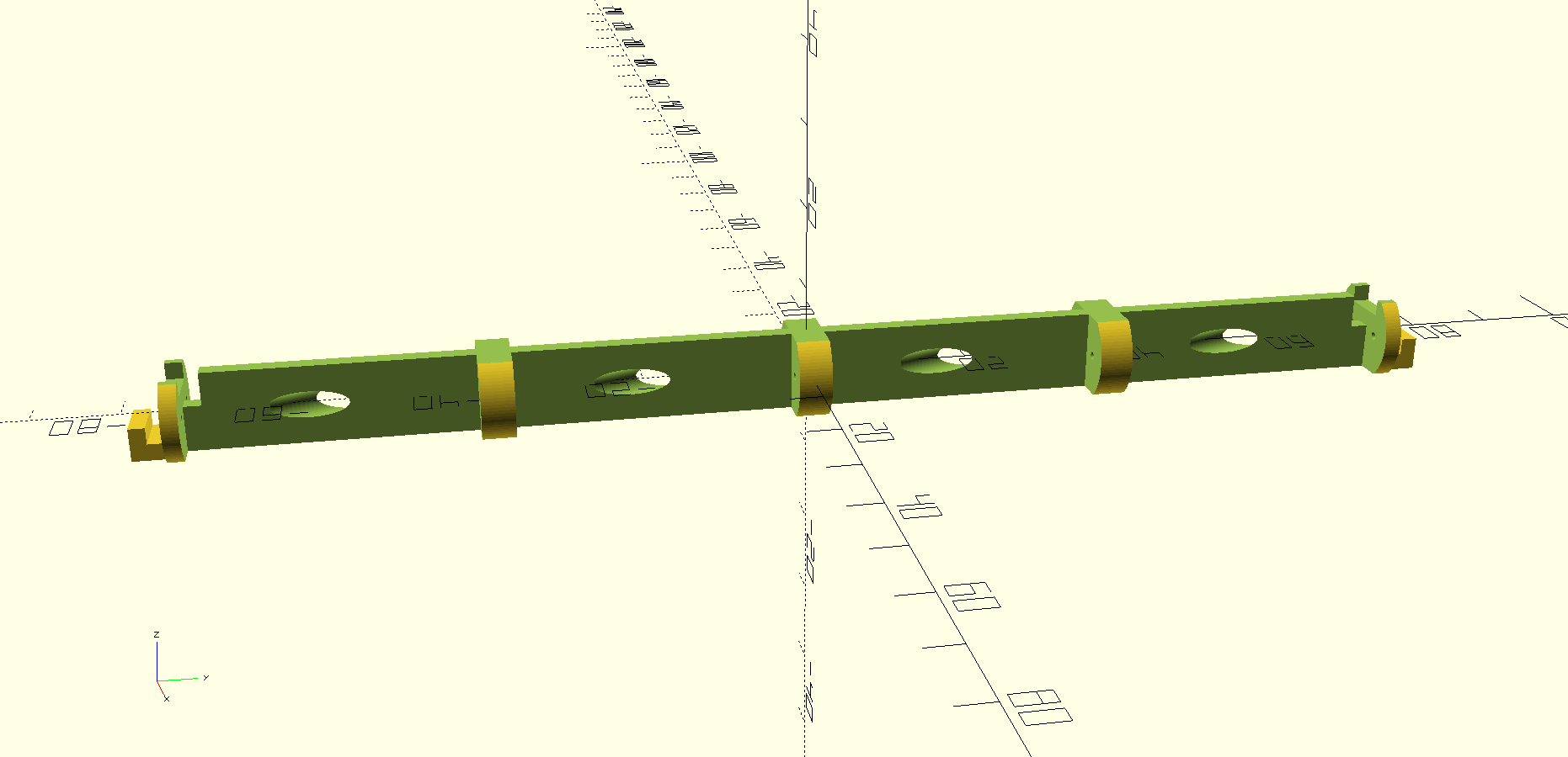
The fixtures provide mechanical support to the reed switches and resistors, which are connected with solder joints.
Additionally:
- they can be clicked together, allowing the chain to be assembled in modules
- they make soldering easy by holding the reed switches into place
Enclosure
I use 16mm (outer diameter) PVC electricity tubing. This means the fixtures need to fit into the 13mm (inner diameter) tube. The PCB with electronics also has to fit the tube, hence the slim form factor.
To make a watertight seal between the wire and the tube, I use grommets. A M25 grommet can clamp onto the tube, a smaller one onto the cable. I designed a cylinder with tapered M25 and M12 holes on the ends. The cylinder has metric thread already in the design, and the grommets screw right in.
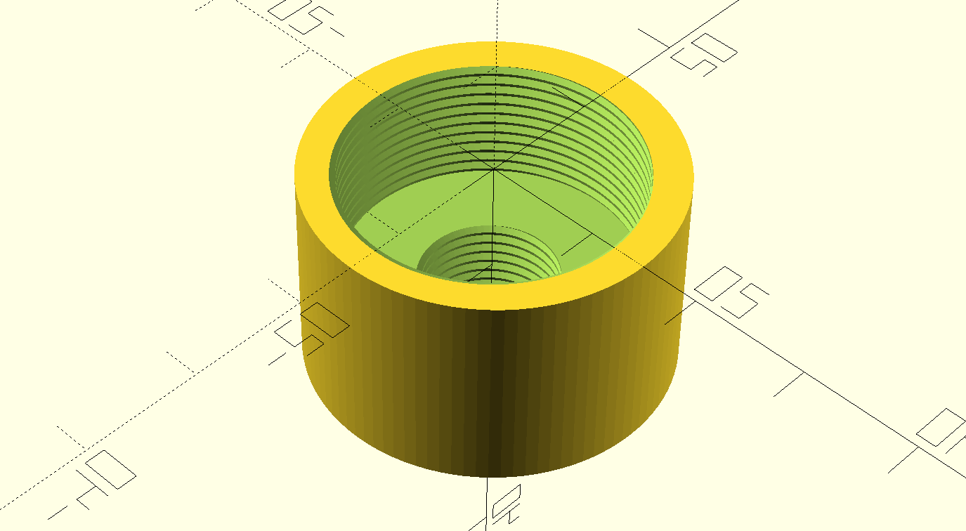
Grommet joiner
The bottom of the tube is supposed to be glued to an end cap with PVC glue, but these are not widely available, so I'll have to improvise.
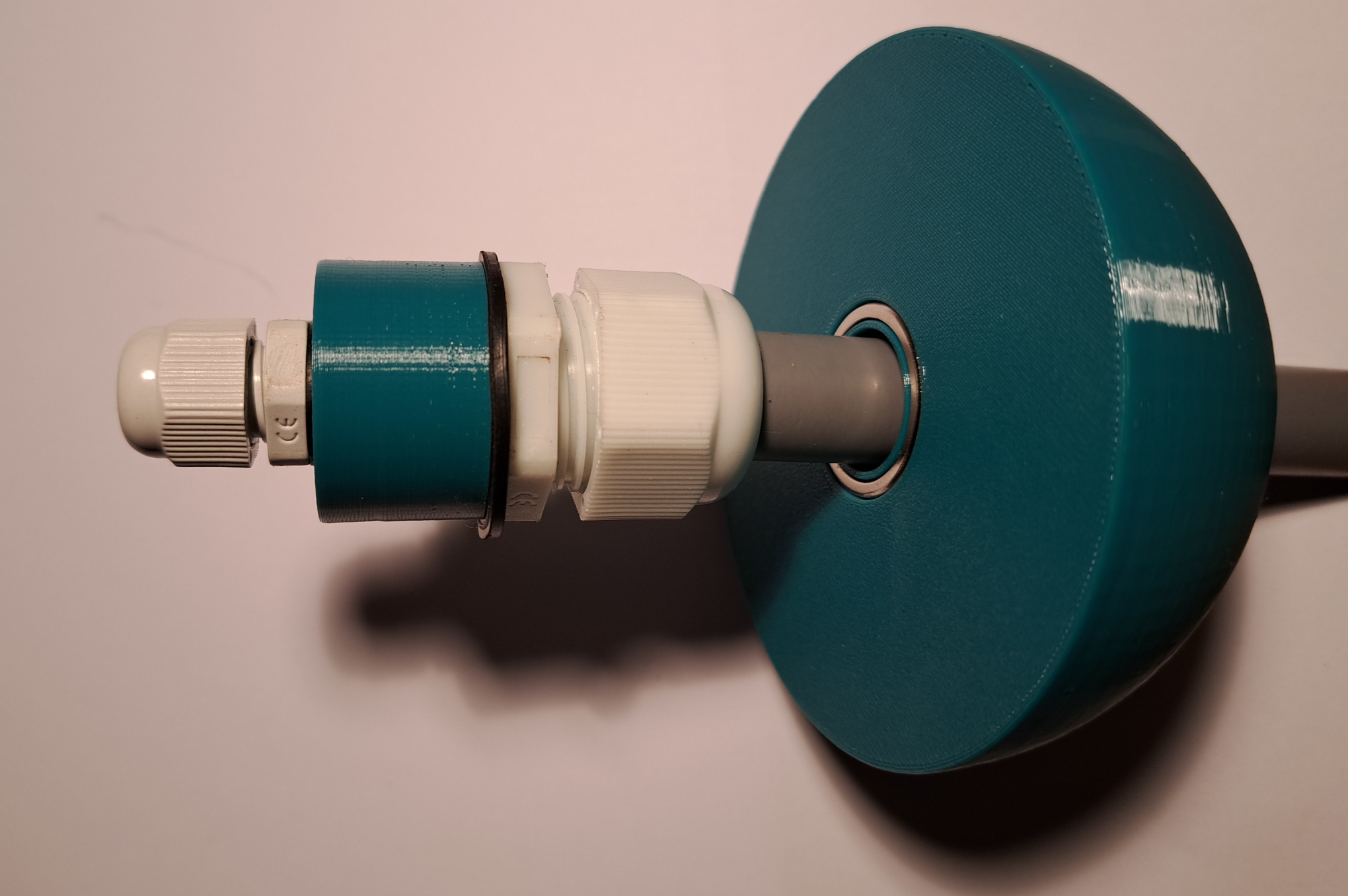
Assembled grommet joiner
The mechanical design files can be found in my reedlevelsensor github repository
Floater
Instead of using a sphere shaped floater, I opted for a sphere cut in half so the floater would be faster to print. The top side has a cut-out for two ring shaped neodymium magnets.
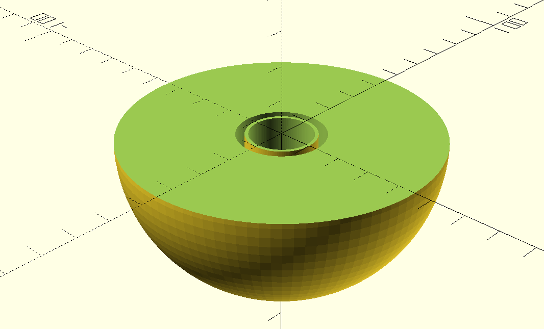
A render of the floater
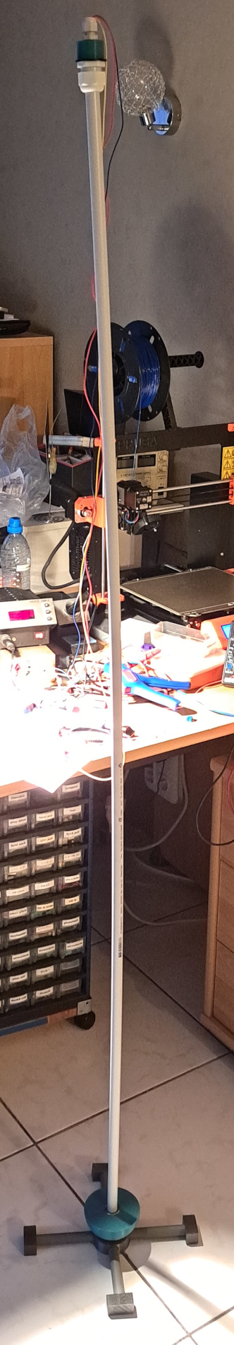
stand
I created a simple stand that helps the sensor stand upright. This makes testing easy and allows the sensor to be pulled out and placed back into the tank easily.
Reed ladder assembly
part of the resistor chain.
3D printed fixture preparation
- remove any overhangs
- remove stringing
- remove hangovers in reed openings
component preparation
- reed switches (Aliexpress): cut the legs in half
- resistors 20 Ohm 1% (Aliexpress): cut the leads so each side has a length of resistor as leg
- Tinned solid core copper wire
I used tinned solid core copper wire I got years ago from a scrapyard that used to be part of a wire harness. After stripping off the insulation I straightened the wire by giving it a yank with two pliers (a bank vise, plier and hammer also work).
soldering
First a little terminology
- common wire side; wire that all the reeds will short to
- signal wire: wire side with the series resistors
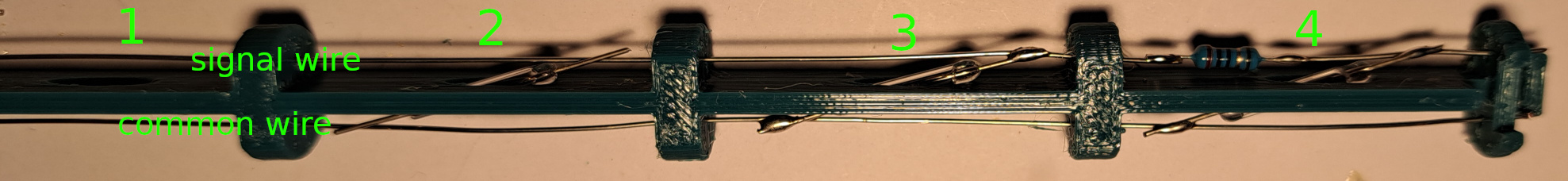
① Cut the wire to length, and inserted it into the holes they should stick out a bit (5mm) at each side. For now I'll call these wires running both through the fixture the bus bars.
② Next I insert the reed switches, so that they hang on top of the bus bars.
③ Solder both ends of the reeds to the bus bars.
④ On the signal wire side,
- cut the wire halfway the reed.
- Cut the signal wire downstream for a bit over the length of a resistor to create a gap to solder the resistor into the signal wire chain.
- Put some solder on the ends of the cuts.
- Solder the resistors in the openings.
⑤ Clip the common and signal wire so there are no conductors in the holes at the opposite sides of each module.
connecting the fixtures
After soldering all the fixtures, they can be clicked together, taking care that all reeds are in the same orientation and the signal side and common wire sides align.
When clicked together, a small piece of wire is inserted and soldered into the common and signal wires.
Final assembly
The complete assembly is composed of:
- 16mm electricity tube
- end cap to plug the tube
- reed fixtures, interleaved flipped and not flipped versions, chained together
- an empty fixture to provide some vertical offset and short together the bus.
Care should be taken to align the fixtures correctly:
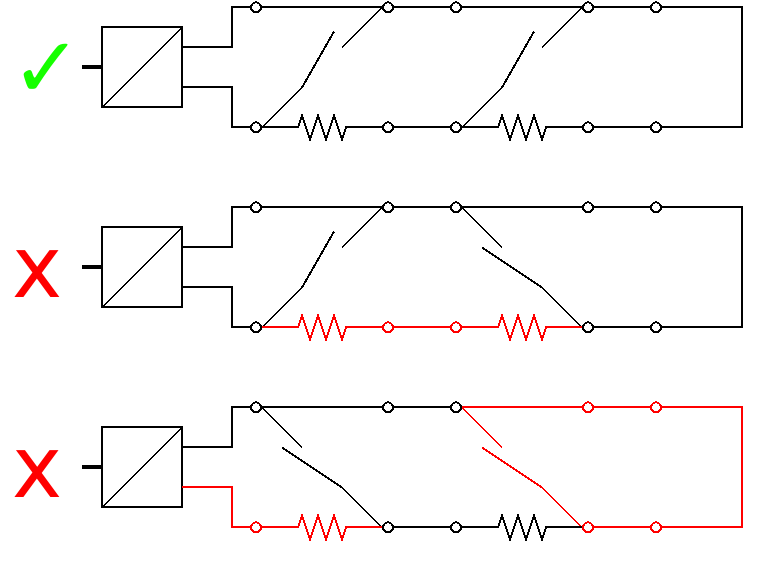
do, don't
To achieve this, the fixture has two versions, the reed switches are 180degrees rotated.
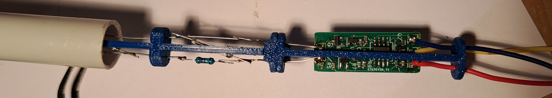
electronics at the end of the tube
Installation
I made a terminal block that fits the tube, the metal parts are used from damaged pcb terminal blocks.
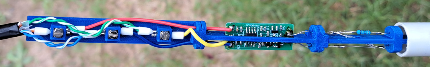
sensor connected to cable
After closing the grommets the tube is lowered into the tank:
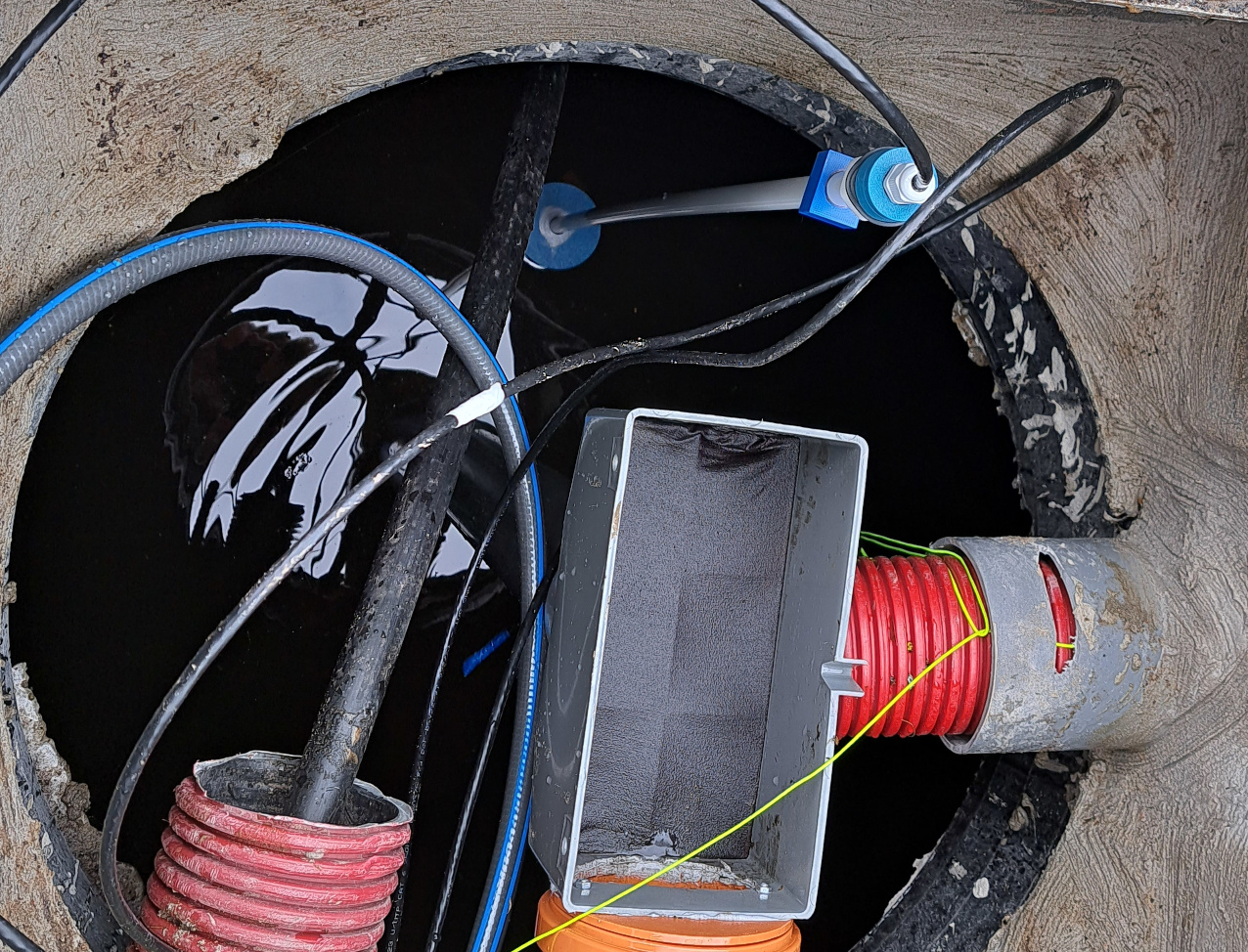
the sensor installed in the tank
Initial Home assistant integration
To check the behavior of the sensor, I used a simple esphome to bring the signal into home assistant for logging.
I had ordered this simple current to voltage converter with offset and gain setting.
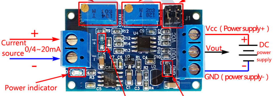
To have a quick solution, I hooked this up straight into an esp32/esp8266's ADC.
However I need to replace it with a simple resistor and add some capacitors since there is quite some noise visible.
substitutions:
  hostname: kot

esphome:
  name: ${hostname}
  platform: ESP8266
  board: nodemcuv2

wifi:
  password: !secret ssid
  password: !secret wlan
  domain: !secret domain

# Enable logging
logger:

# Enable Home Assistant API
api:
  password: !secret api
ota:
  password: !secret ota
sensor:
  - platform: adc
    pin: A0
    name: "rainwater tank"
    icon: "mdi:cup-water"
    update_interval: 2s
    unit_of_measurement: "%"
    accuracy_decimals: 1
    filters:
# 3.3V = 20mA
      - multiply: 6.06
#now in mA, 4-20mA
      - offset: 4
# now 0-16mA
      - multiply: 6.25
# now 0-100
      - lambda: return 100 - x;
      - sliding_window_moving_average:
          window_size: 30
          send_every: 30
#losing 10cm of 1.5m, of 7500L
#      - multiply: 70
# now in liters
This can be up and running with simple commands (if a secrets.yaml with secrets is present next to it).
esphome compile kot.yaml
esphome upload kot.yaml
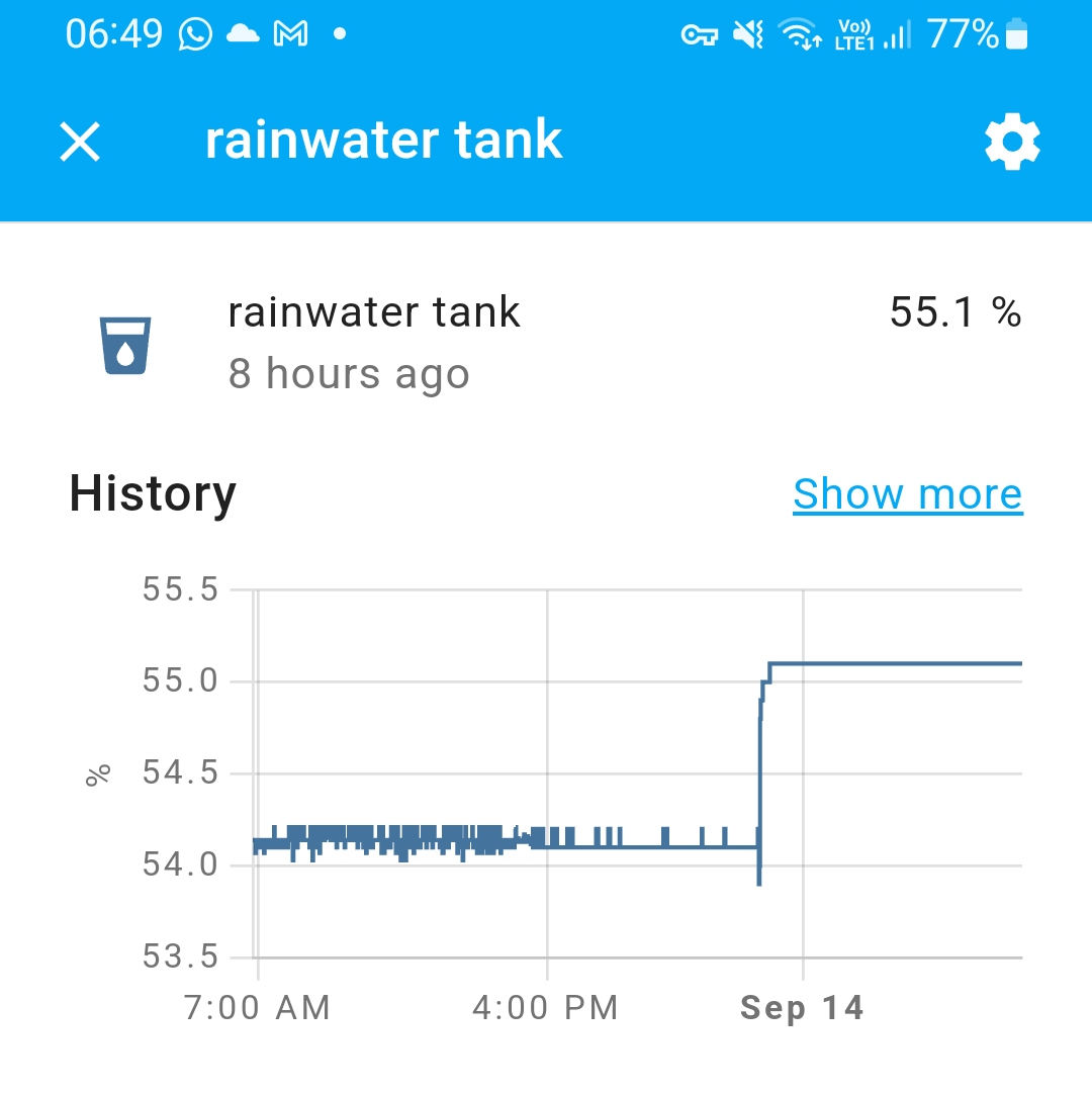
Home assistant history (first sensor step observed)
Long term Home assistant integration
I'm planning to to sense everything via modbus, so i got one of these current loop to modbus converters to see if it is usable:
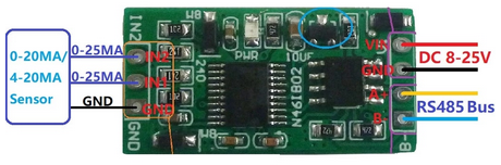
I plan to try the modbus integration and a raspberry pi running mbusd or ESP32 with a serial to TCP server.
Liked something? Worked on something similar? Let me know what you think on Mastodon!
You can use your Mastodon account to reply to this post.