First steps with the PICmicro
In the year 2001 I became very interested in digital electronics, and wanted to start experimenting with microcontrollers. When I was about to buy (expensive) Basic Stamps, I found the JAL website, and read the Hello World material. The JAL language targeted the Microchip PIC controllers.
Introduction
The Basic Stamp was basically a PIC with proprietary firmware, combined with a serial EEPROM that held the basic code.
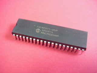
When I compared the cost difference and the advantages of using JAL and a PIC, I was quickly convinced to start with JAL, and ordered some PIC16F877 microcontrollers from Wouter Van Ooijen, preprogrammed with his handy bootloader, so I could get started quickly. By the summer that year they arrived by mail. Since then I learned a lot about microcontrollers and digital electronics..
Pic Development
When I got the PIC16F877 chip with Wloader, I believe I got the most powerful, yet easy to use microcontroller experiment system a newbie can get. The Wloader allowed me to quickly upload source code using only a RS232 level shifter, whilst not having to sacrifice the asynchronous port to upload firmware.
The PIC16F877 features the following built in peripherals:
- 8K of flash program memory
- 8 bytes of RAM, 256 bytes of Data EEPROM
- a 10-bit analog-digital converter module (8 channels)
- 3 timers,two 16-bit Capture/Compare/PWM modules
- a synchronous serial port (SPI and I2C), and an asynchronous serial port
My PIC prototyping board
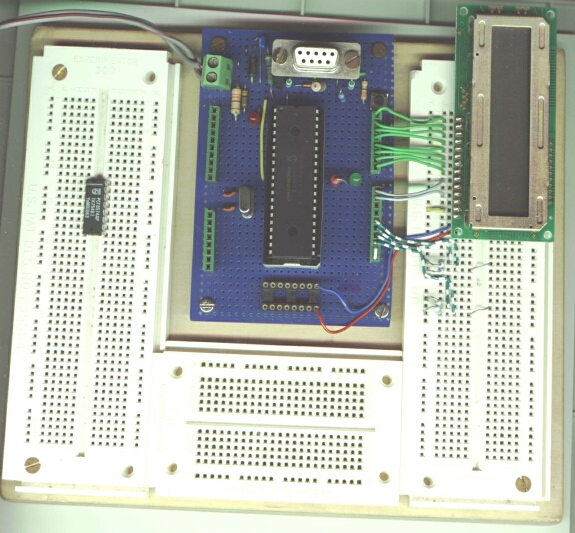
As you can see in the picture above, I built an experiment board, with three breadbords, and a blue perfboard with the PIC in the middle, you also can see a part of my common breadbord setup; an LCD is plugged onto the breadbord, and the green-white wires are used for the connection between the PIC and 4 switches which I removed (the board wasn't stable under our flatbed scanner because the switches were higher than the other components :-) )
The cable on the top left is connected to the power supply. You also can see the DB9-F connector to program the PIC. Those green connectors next to the PIC are connections to the ports. Top left: MCLR,port A,port E. Lower right: port C. Top right: port B. Lower right: Port D. On the bottom of the blue print, you can see a 16 pin IC foot. The upper row is connected to 0V (-) and the lower row to 5V (+).
This is the PIC controller print of a friend of me. When he saw my experiment plate he wanted to have one too. So I ordered a PIC for him too. Building it went slower than my first development plate; but I think that's because he wouldn't let me build it alone ;-).
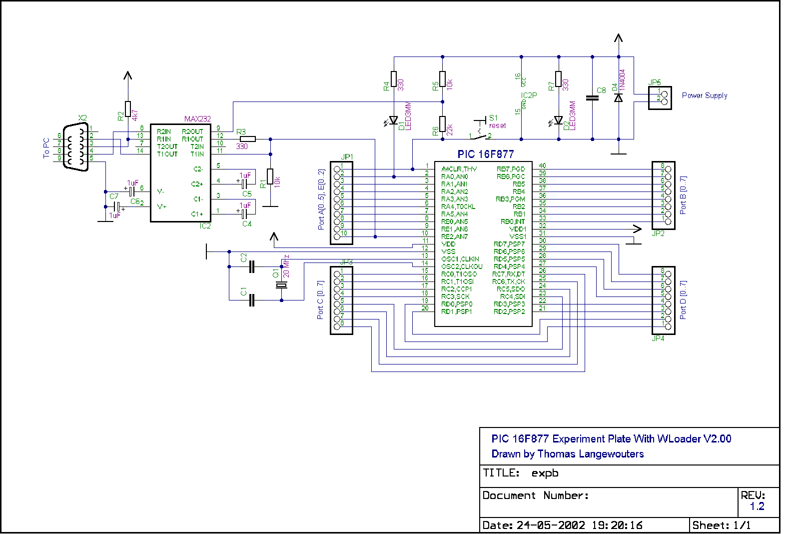
Schematics
Of the Experiment plate with the new WLoader which uses a MAX232
Liked something? Worked on something similar? Let me know what you think on Mastodon!
You can direct-message me, or mention me @thouters@hsnl.social