OpenPlank Proof Of Concept
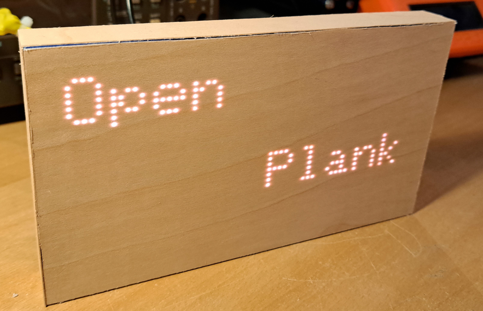
The first (crude) prototype with sloppy veneer edges
In November 2022 I saw a cool device at a Matter event. The device was presented as an unobtrusive way to interact with technology. Unlike usual touch screen devices, it looks like a wooden plank that is sensitive to touch and uses a LED pixel matrix behind the wood to visualize icons and text.
Since the device wasn't available for sale, I wondered how easy it would be to DIY a (much) simpler version that I could use for some of the same tasks.
I worked on this for a few hours each week, and by the end of December I had this simple proof of concept, making use of cheap parts and easy to assemble.
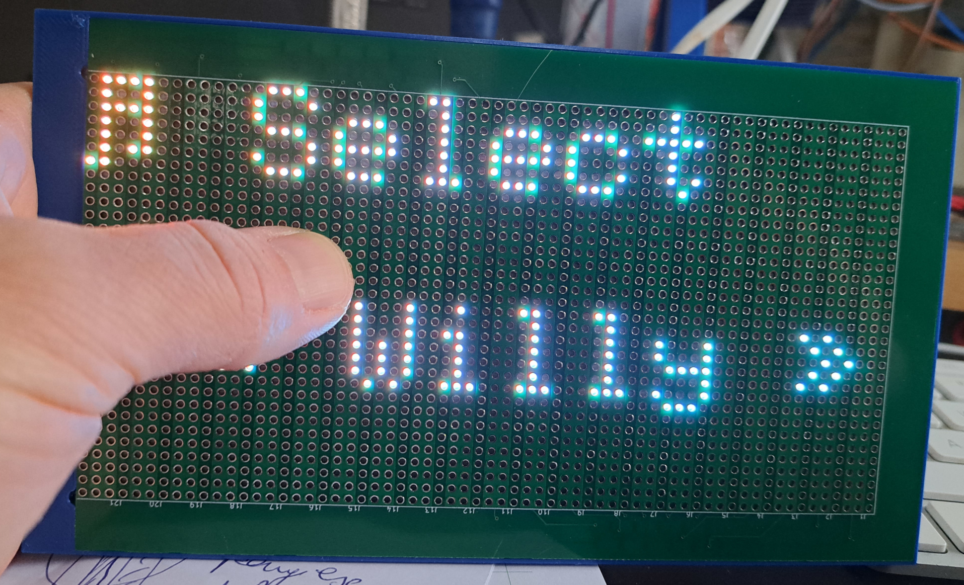
I call it the OpenPlank. Check it out...
LED Display
I started this project by looking at the options for the LED display that were available. I found that there are Chinese LED matrixes on the market that you go by the search term 'HUB75 P2.5', where the P2.5 stands for the pitch between the LED pixels(in this case 2.5mm). The most pixel-dense displays I found have a 1mm pitch, and there are more coarse displays with eg 5mm pitch.
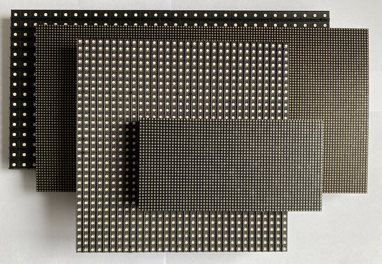
I opted for a P2.5 display since that would work with the idea I had for the touch input.
These displays can be daisy-chained; they can be connected together and driven as a single larger display.
HUB75 interface
I found and used the PxMatrix library, which was easy to set up and to get working. I found out that the display I had has a 1/16 configuration. The display is driven using a SPI host and the signals are wired in such a way that it is configured as one large shift register. For more information about HUB75 display matrices, you can read this sparkfun article or search the web.
Input
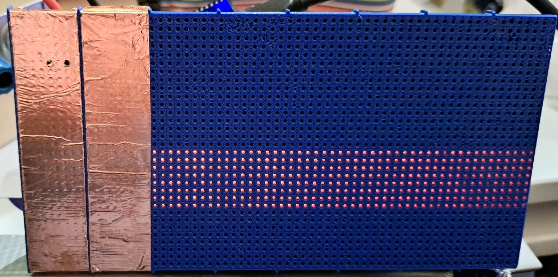
To avoid a complicated touch layer design, I wanted to check if a circuit board with vertical copper strips could provide a simple one dimensional (along the X axis) input.
I designed a cover with 'sieve' hole pattern grid and printed it. I then cut and applied a few strips of copper tape to see if a touch controller I had on stock would sense the touch when the veneer was held before it.
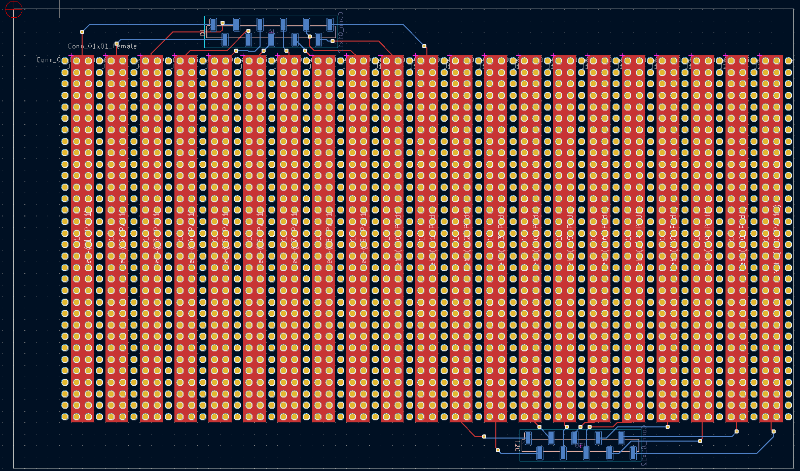
This worked, so I quickly hacked together a design in KiCAD.
Touch layer circuit board
I made this design simple and quick, its main features are:
- The 1.2mm holes are aligned with the LED's
- It has a 10mm bezel around the display that can be used as glue surface.
- There is no bezel on right side so two boards can be put next to each other seamlessly
- there are 2.54mm pitch SMT connectors on back to plug the MPR121 boards onto.
Once consideration with this setup is that the holes need to be aligned with great care, since the RGB LED pixels are made out of three LED dies that are slightly offset. Misalignment would block one of the colors partly. Fortunately the veneer diffuses the light and makes it less of an issue.
Touch digitizer
I started with MPR121's since I already had a few of these boards from a previous project. They can be arranged in a grid too to create a 5x7 or 4x8 grid.
As an alternative I found a software library to do touch using only a simple analog mux (documentation for it can be found here). This has some special microcontroller requirements, but could still be an option.
Device input backup plan
In case the touchscreen approach would not work, I also have some gesture sensor I can use (APDS-9960 Gesture sensor if I recall correctly). I may add it anyway to automatically wake up the device when a hand gets near it.
Chassis
As initial prototype I designed a chassis (plural chassis /-iz/ from French châssis, the load-bearing framework of an artificial object) that holds a single display. The chassis has:
- a 1mm bezel around the touch PCB which keeps it in place for alignment when glueing.
- 10mm glue contact bezel with the touch PCB
- openings for the touch PCB's connectors.
- slots to insert discs behind the LED board to keep it in place but easy to remove.
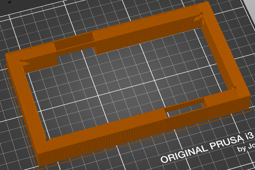
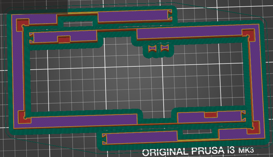
Double size chassis
A chassis around two displays would be too big for my Prusa MK3's printbed, so I designed one that uses Butterfly joints to connect both parts. This fits together perfectly with the butterfly joints, and feels quite solid.
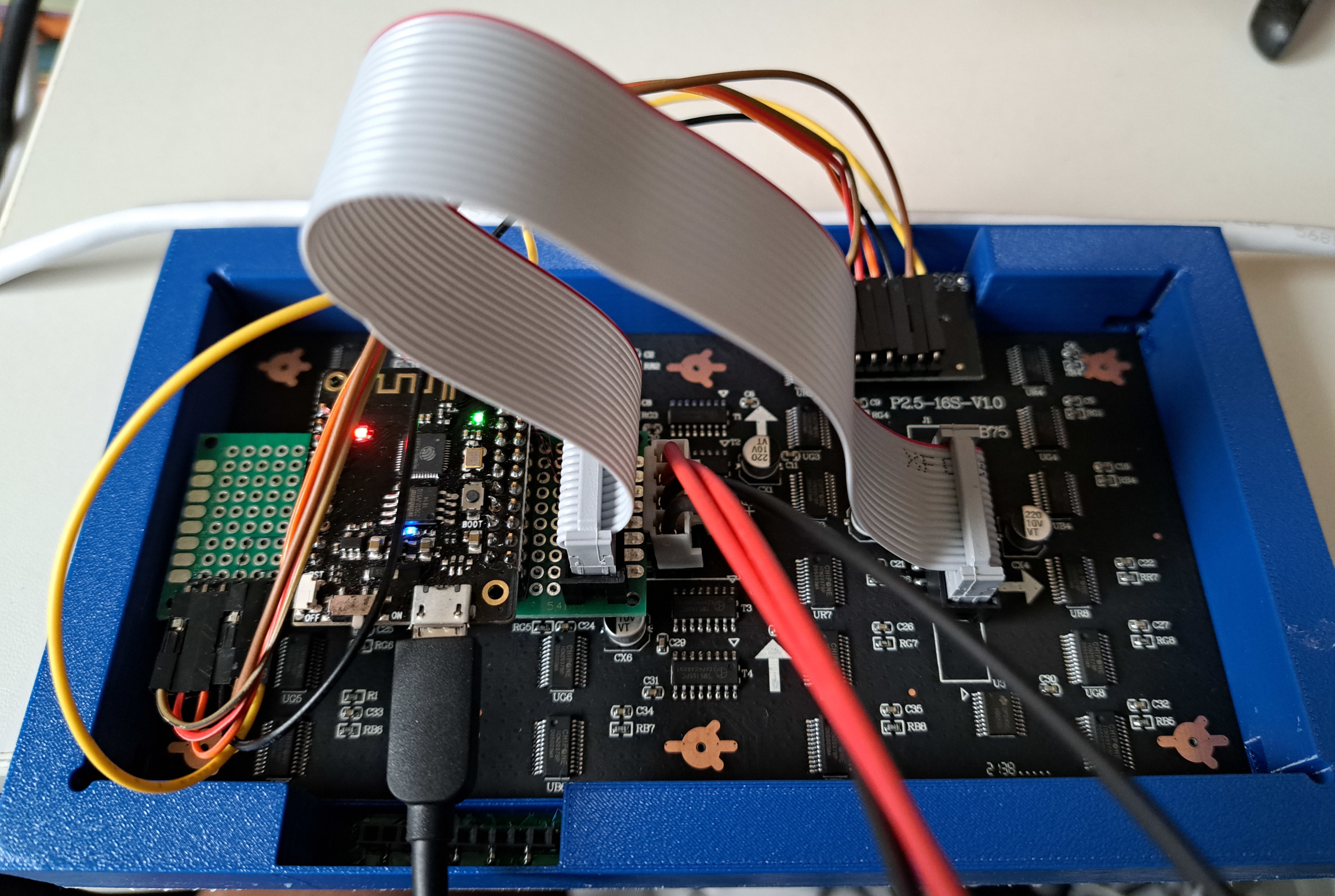
Mechanical assembly
I printed a plastic block a bit smaller than the display to apply pressure to the touch PCB from the back when clamping for glueing, and four brackets that hold the bezel's Y dimension together.
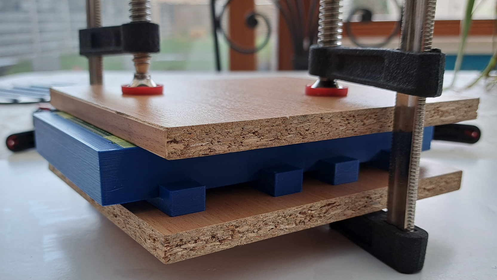
I used a transparent contact glue, applied with a conference badge as spatula but a credit card sized plastic card would also work I think.
Both parts are plastered with the glue using the spatula, left to dry for 10 minutes and afterwards put together and rubbed to remove air (check youtube for video's on how to apply veneer).
Before applying glue it is important to use painter's masking tape to cover surfaces that should not get glue onto them, as well as the backside of the touch board so glue does not get pushed trough the holes.
After glueing the PCB onto the chassis body, the wood veneer (I used Cricut maple veneer) is glued to the PCB, trimming the edges must be done carefully, since you can easily cut off too much, as I did with my first prototype.
User Interface
I plan to use LGVL - Light and Versatile Graphics Library to make the user interface as generic as possible and to reuse things like swipe detection and widgets.
It will need to run in a monochrome mode, with a small framebuffer and tiny fonts. It may also require some rewriting of the rendering code that renders widgets too large by default. Writing some glue code to feed LVGL's pixel output to the HUB75 driver will also be needed.
I found a nice article on using LVGL with monochrome displays which makes it look easy.
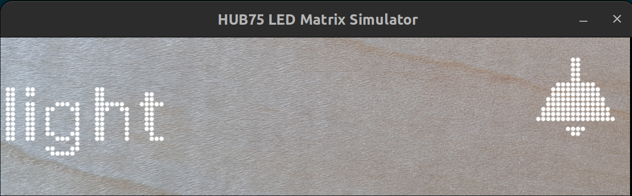
Simulator
While waiting for parts, I started working on a PC simulator which renders the LVGL framebuffer pixels on an SDL surface as round pixels.
The simulator is still in early stages, since the electronic and mechanical parts arrived quickly and writing some proof of concept software for it only took a few minutes.
It should also include downsampling of touch events to match the coarse touch PCB. This way the user interface can be a realistic representation of the hardware. I plan to also use it to check if this setup is good enough to use slider widgets.
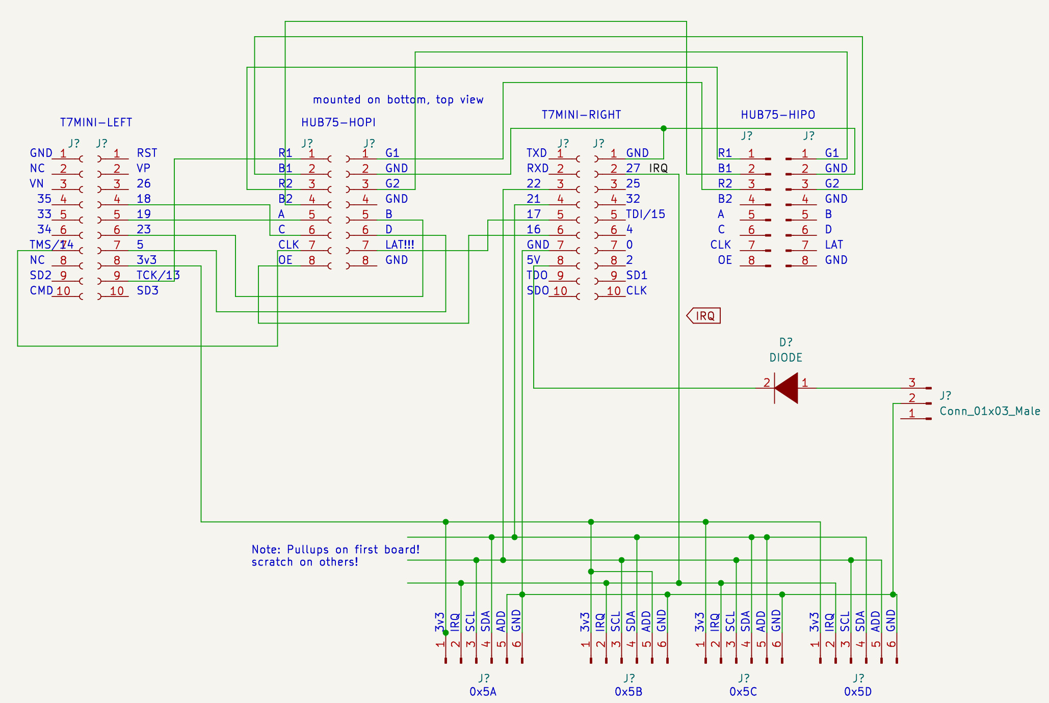
Circuit
This circuit is based on the PxMatrix wiring, along with a simple I2C bus for the MPR121 touch modules.
Design Files
POC touch test/demo
This platformio project uses the adafruit graphics API of the PxMatrix library to light up verical bars of the openplank touch PCB when they are touched. The Adafruit MPR121 library is used to read out two MPR121 chips.
PC Simulator
This platformio project uses a hacked version of the lv_drivers SDL backend for LVGL to render the framebuffer pixels as 10x10px circles on a background image of a wooden plank.
Chassis design files
This OpenSCAD code models the chassis of the OpenPlank
https://github.com/thouters/openplank-chassis
Chassis STL object
https://www.printables.com/model/373360-openplank-mk0-12-chassis
Work in progress
You can follow me on Mastodon to read updates on this project.
Liked something? Worked on something similar? Let me know what you think on Mastodon!
You can use your Mastodon account to reply to this post.