Rollershutters control panel
Shutter control panel
When we renovated our living room, we upgraded the window roller shutters with electric motors. While we usually only open and close all of them together, we still want to be able to set them to individual positions. I decided to make a central control panel with 6 physical buttons and implement some logic in the Siemens Logo controller to control the motors.
Goal
My goal was to create a simple control panel that makes the following things easy:
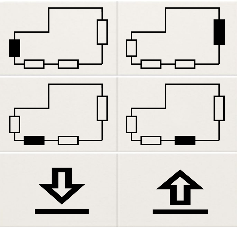
- Open and close all rollers with a single button push (⇩/⇧)
- Open and close individual shutters with two (or more) button pushes (roller button(s) + ⇩/⇧)
- Stop the movement by hitting the ⇧ or⇩ button again.
The power is cut to the motors after a timeout.
I drew a state diagram illustrating the operation:
State diagram.
Parts
Buttons
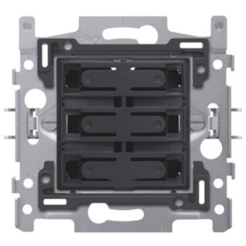
6 way Pushbutton
The 6 way Niko button pad from the product family I bought the rest of our switching gear from was very expensive (80€). The plastic button cover available in many colors is only a few euro's. That opens experimentation options, and I plan to laser engrave the icons on top at one point.
Motor
The roller motors are controlled with two 230V signals, one to run up, one to run down. Only one of these should receive line voltage, or the motor stalls. The motor has internal end stops which are calibrated on installation time, so it can be left powered.
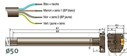
Motor diagram
Controller
The central Siemens mini-PLC controls the motors:
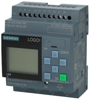
Siemens logo PLC
I always buy the 24V version with transistor outputs, and use interface relays.
Relays
The Schneider Harmony (24V coil voltage) interface relays control the mains voltage.
I originally planned to use one of these hooked up to the neutral of each motor, and one for each direction:
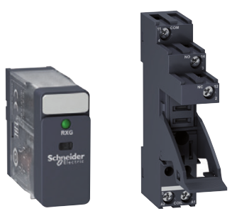
single pole make and break relay
By having one single pole relay per motor, I planned to reduce the number of outputs from 8 to 6, and occupy minimal cabinet space. However, leaving some motors neutral floating while having the control lines connected to other motors draws current through the floating motors, which makes that configuration unusable.
For that reason I had to use the dual pole variant as roller selector. By The way these relays can be operated manually and locked into position in case of 24V PSU failure.
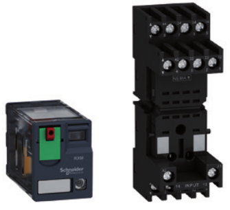
dual pole make and break relay
Circuit
High voltage drivers
Relay schematic, example with only two rollers
This relay circuit makes it impossible to connect both direction lines to the line voltage. The up direction is prefered in case both directon relays are energized.
Input
The human interface is as simple as can be, the 6 momentary button switches are feeding 24V to the LOGO! inputs when pushed.
Siemens Logo logic
Logo configuration diagram
The LOGO! configuration is pretty simple, it consists of these parts:
- A SET/RESET flipflop with pulse input per relay
- The B054 timer triggers the flipflop RESET inputs 30seconds after a button push, clearing all state.
- B058/B059/B060 set all roller selectors if the ⇧ or ⇩ button is pressed and no roller is selected.
Liked something? Worked on something similar? Let me know what you think on Mastodon!
You can use your Mastodon account to reply to this post.